15
Packaged and Split Rooftop Ventilator
© 2021 Mitsubishi Electric US, Inc.
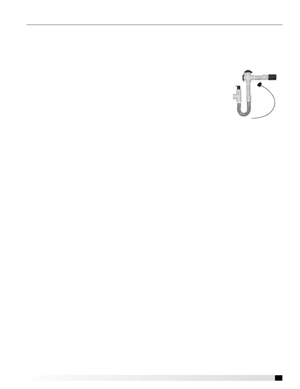
Condensate Drain Trap
This unit is equipped with a stainless steel condensate
pan with a stainless steel connection. It is important that
the drain connection be tted with a “P” trap to ensure
proper drainage of condensate while maintaining internal
static pressures and to prevent migration of sewer gas
back into the unit.
A “P” trap assembly (kit) is
supplied with each unit, except
for housing 5-1, and
is to be assembled and
installed as local conditions
require and according to the
assembly instructions
provided with the “P” trap.
If local and area codes permit,
the condensate may be drained
back onto the roof, but a drip pad should be provided
beneath the outlet. If local and area codes require
a permanent drain line, it should be fabricated and
installed in accordance with Best Practices and all
codes.
In some climates, it will be necessary to provide freeze
protection for the “P” trap and drain line. The “P” trap
should be kept lled with water or glycol solution at all
times and it should be protected from freezing to protect
the “P” trap from damage. If severe weather conditions
occur, it may be necessary to fabricate a “P” trap and
drain line of metal and install a heat tape to prevent
freezing.
Condensate Overow Switch
This unit is equipped with an optional factory-mounted
condensate overflow switch. In the event that a high
level of condensate is detected, the microprocessor
controller will trigger an alarm and shutdown the unit.
Optional Coil Piping
Factory-installed cooling components are mounted in the
coil section of the unit. The coil section is downstream of
the energy wheel on the supply air side of the unit.
Optional hot water coil is located downstream of the
supply fan on all models. Water piping can be routed
through the base of this unit if desired.
Piping vestibule is available for all models.
Water Coils
1. Piping should be in accordance with accepted
industry standards. Pipework should be supported
independently of the coils. When installing couplings,
do not apply undue stress to the connection
extending through the unit. Use a backup pipe
wrench to avoid breaking the weld between coil
connection and header.
2. Connect the water supply to the bottom connection
on the air leaving side and the water return to the
top connection on the air entering side. Connecting
the supply and/or return in any other manner will
result in very poor performance. Be sure to replace
factory-installed grommets around coil connections
if removed for piping. Failure to replace grommets
will result in water leakage into the unit and altered
performance.
3. Water coils are not normally recommended for
use with entering air temperatures below 40°F. No
control system can be depended on to be 100% safe
against freeze-up with water coils. Glycol solutions
or brines are the only safe media for operation of
water coils with low entering air conditions. If glycol
or brine solutions are not used, coils must be drained
when freezing conditions are expected. If required,
vent and drain connections must be field-piped,
external to the unit.
4. Pipe sizes for the system must be selected on the
basis of the head (pressure) available from the
circulation pump. The velocity should not exceed
6 feet per second and the friction loss should be
approximately 3 feet of water column per 100 feet
of pipe.
Water Coil Piping Installation