20
Packaged and Split Rooftop Ventilator
© 2021 Mitsubishi Electric US, Inc.
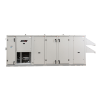
Control Center Components
Main Control Center Components
Image represents a typical installation for MP-1-1 or MPE-2-1. Components and locations will vary on
MPE-4-0,-5-1, MP and MPF models.
Electrical Cabinet
1. Power distribution block; high voltage
supply is terminated here
2. Fuse holders
3. Phase monitor
4. Unit Disconnect
5. Condensing fan motor contactors
6. Wheel motor contactor
7. Compressor motor contactors
Controls Cabinet
8. Transformer
9. VFDs
10. Microprocessor controller
11. Monitoring points
12. Low voltage terminal strip
13. Relays
14. Dirty filter switches
15. Wheel pressure switch
16. Outdoor airflow monitor
17. Exhaust airflow monitor
18. Digital scroll controller
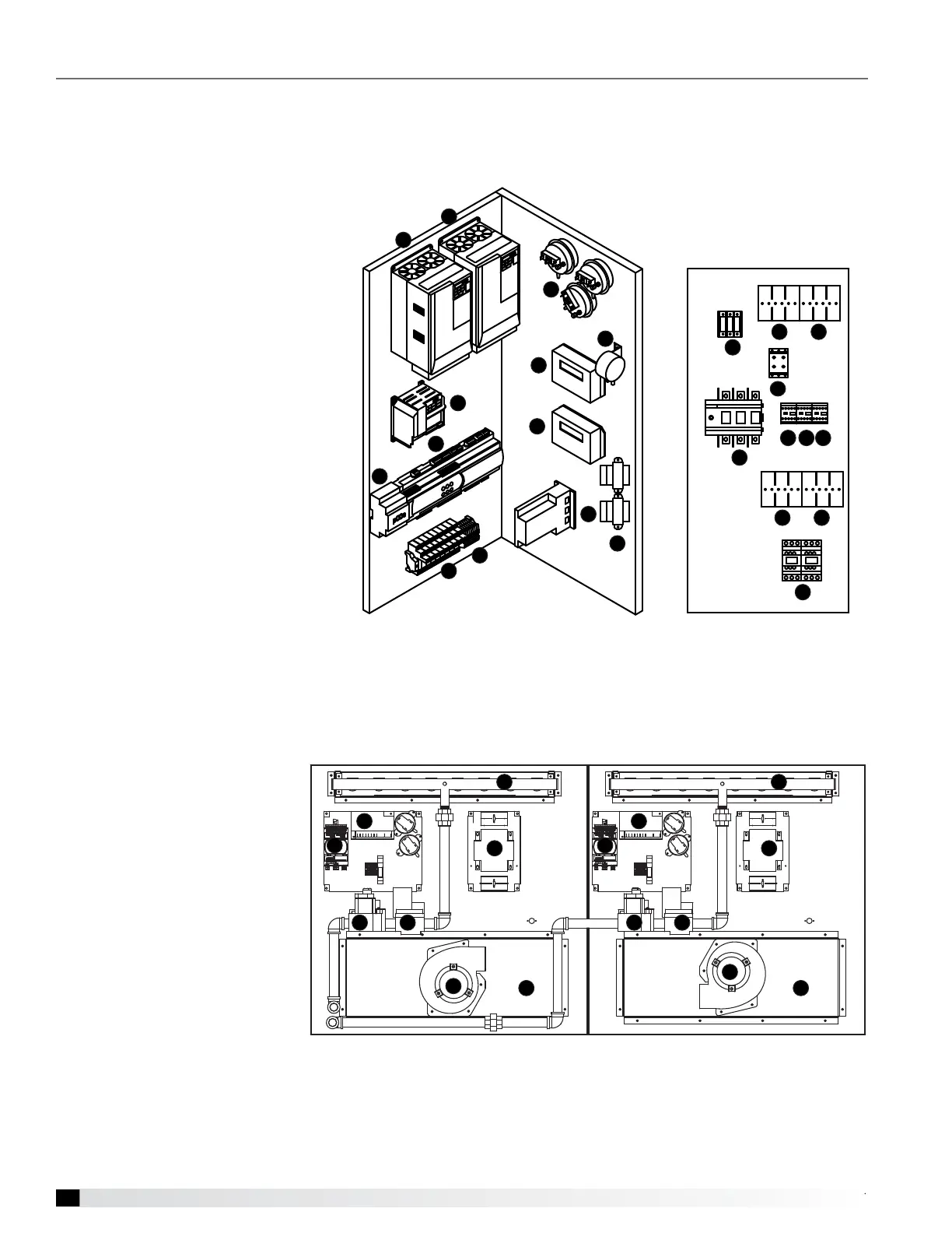
Optional Indirect Gas-Fired Furnace
Note: In some models, two furnaces are installed to provide greater output. When two furnaces are installed, they are
in parallel and both will operate at the same time and the same output. Both furnaces will have identical controls.
1. Single-stage valve
2. Modulating valve
3. PCOE expansion board
4. Ignition controller
5. Transformer
6. Combustion blower
7. Burner manifold
8. Collector box
For further information on the optional furnace and its control center, see the Indirect Gas-Fired Heat lOM shipped
with the unit.
Electrical Cabinet
Controls Cabinet
7
1
3
5
6
8
2 2
5
14
15
16
17
18
13
12
11
10
9
9
9
4
Accessible via control center door
Accessible via compressor door
2 2
5
1
2
4
3
6
7
8
5
1
2
4
3
6
7
8