EasyManua.ls Logo

Premisys MP Series User Manual

Premisys MP Series
40 pages
To Next Page IconTo Next Page
Page #1 background imageLoading...
Page #1 background image
Installation, Operation and Maintenance Manual
Please read and save these instructions for future reference. Read carefully before attempting to assemble, install,
operate or maintain the product described. Protect yourself and others by observing all safety information. Failure
to comply with instructions could result in personal injury and/or property damage!
1
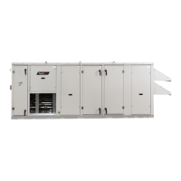
Packaged and Split Rooftop Ventilator
PremiSys
General Safety Information
WARNING
The roof lining contains high voltage wiring. To prevent
electrocution, do not puncture the interior or exterior
panels of the roof.
DANGER
Always disconnect power before working on or near
this equipment. Lock and tag the disconnect switch or
breaker to prevent accidental power up.
If this unit is equipped with optional gas accessories,
turn off gas supply whenever power is disconnected.
CAUTION
This unit is equipped with a compressed refrigerant
system. If a leak in the system should occur,
immediately evacuate the area. An EPA Certified
Technician must be engaged to make repairs or
corrections. Refrigerant leaks may also cause bodily
harm.
CAUTION
When servicing the unit, the internal components may
be hot enough to cause pain or injury. Allow time for
cooling before servicing.
Only qualied personnel should install and maintain this
system. Personnel should have a clear understanding of
these instructions and should be aware of general safety
precautions. Improper installation can result in electric
shock, possible injury due to coming in contact with
moving parts, as well as other potential hazards. Other
considerations may be required if high winds or seismic
activity are present. If more information is needed,
contact a licensed professional engineer before moving
forward.
1. Follow all local electrical and safety codes, as well as
the National Electrical Code (NEC), the National Fire
Protection Agency (NFPA), where applicable. Follow
the Canadian Electrical Code (CEC) in Canada.
2. All moving parts must be free to rotate without striking
or rubbing any stationary objects.
3. Unit must be securely and adequately grounded.
4. Do not spin wheel faster than maximum cataloged
fan RPM. Adjustments to fan speed signicantly
affect motor load. If the fan RPM is changed, the
motor current should be checked to make sure it is
not exceeding the motor nameplate amps.
5. Verify that the power source is compatible with the
equipment.
6. Never open access doors to the unit while it is
running.
Models MP/MPE (Packaged DX) Model MPF (Split DX)
Document 479650
Models MP, MPE and MPF
Packaged and Split Rooftop Ventilator
© 2017 Mitsubishi Electric US, Inc.
Premi
Sys

Table of Contents

Questions and Answers:

Premisys MP Series Specifications

General IconGeneral
BrandPremisys
ModelMP Series
CategoryFan
LanguageEnglish

Summary

General Safety Information

Receiving, Handling, and Storage

Inspection and Maintenance

Monthly inspection of units in storage, checking for moisture or dirt and performing maintenance.

Removing from Storage

Inspect unit assembly before final installation and check fasteners and rotating parts.

Product Overview

Cooling Options

Units have packaged DX or split DX cooling options available.

Heating Options

Offers indirect gas-fired furnace, electric heat, or hot water coil as heat sources.

Airflow Arrangement

Unit is capable of Constant Air Volume (CAV), Variable Air Volume (VAV), 100% Outdoor Air.

Safety Listing

Models are listed per ANSI/UL 1995, Heating and Cooling Equipment and are ETL Certified.

Models and Capacities

Details specific models, cooling capacities for Packaged DX and Split DX systems.

Supplemental IOM Manuals

Lists additional manuals for heat modules, controller, and M-Net connection.

Subassemblies

Blower

Unit features one or two plenum-type fans for supply air and optional exhaust air.

Coils (Packaged)

Includes evaporator, condenser, optional hot water, and optional reheat coils.

Coils (Split)

Includes evaporator, optional hot water, and optional reheat coils.

Compressors

Units have one or two compressors; optional digital scroll or inverter scroll types.

Dampers

Features a motorized intake air damper.

Electric Heater

Optional SCR controlled electric heater with separate power supply.

Filters

Includes metal mesh, pleated paper MERV 8/13, and optional final filters.

Indirect Gas-Fired Furnace

Optional PVG or PVF furnace available on specific housing sizes.

Packaged DX System

Unit may include one or two compressors, condenser, and evaporator coils.

Split DX System

Unit may be ordered with split DX cooling and energy wheel for Mitsubishi outdoor units.

Installation - Packaged DX

Typical Unit Weights and Dimensions

Provides weights, dimensions (L, W, H, J), and filter sizes for Packaged DX models.

Inlet/Discharge Locations

Details dimensions for various inlet and discharge connection points on Packaged DX units.

Service Clearances

Specifies required clearances for access (ACS), control center (CC), and outdoor air (OA).

Installation - Split DX

Typical Unit Weights and Dimensions

Provides weights, dimensions (L, W, H), and filter sizes for Split DX models.

Inlet/Discharge Locations

Details dimensions for various inlet and discharge connection points on Split DX units.

Service Clearances

Specifies required clearances for access (ACS), control center (CC), and outdoor air (OA).

Packaged DX Unit Clearances and Handling

Lifting Procedures

Instructions for safe lifting, including using spreader bars and checking balance.

Field Power Access

Determines placement for high and low voltage wiring entry into the cabinet.

Mounting and Ductwork

Roof Curb Mounting

Guidance on installing factory-supplied or field-provided roof curbs for unit placement.

Ductwork Configurations

Notes on downblast discharge ductwork connections and openings.

Rail Mounting and Layout

Instructions for installing units on provided rails, ensuring proper support and positioning.

Electrical Information

Determine Main Power Line Size

Sizing main power lines based on unit nameplate voltage and MCA.

Electric Heater Wiring

Sizing wiring for optional electric heaters, ensuring compatibility with nameplate ratings.

Electrical Connections

Provides guidance on connecting power supplies, optional outlets, and field-wired components.

Gas and Piping Installation

Electrical and Gas Supply Entry Locations

Recommends entry locations for electrical service, gas supply, and heater wiring.

Indirect-Gas Piping Installation

Details requirements for field-supplied gas supply piping for indirect gas-fired furnaces.

Water Coil and Condensate Drain

Water Coil Piping Installation

Guidelines for connecting water supply and return to coils, and selecting pipe sizes.

Condensate Drain Trap

Instructions for installing a P-trap for condensate drainage and freeze protection.

Split DX Piping Design and Installation

R410A Piping Design - 1-Pipe

Specifies copper pipe types, pressure ratings, and recommended pipe sizes for R410A systems.

Refrigerant Line Sizes

Table detailing refrigerant line connections for DOAS units and outdoor units.

Split DX Refrigerant Piping Lengths

Piping Length Calculations

Details piping lengths, equivalent lengths, and size selection rules for various outdoor units.

Split DX Refrigerant Charge Calculation

Calculating Additional Charge

Guide to calculating additional refrigerant charge based on piping length and size.

DOAS Charge Amount

Provides charge amounts for different DOAS model numbers and factory-charged amounts.

Split DX Piping Connections

Dimensions and Pipe Sizes

Shows connections and dimensions for MPF-1 and MPF-2 housing sizes, and pipe sizes.

Control Center Components

Main Control Center Components

Identifies high and low voltage components within the main control center.

Optional Indirect Gas-Fired Furnace

Describes components and operation of optional dual furnaces for increased output.

Component Operation

Phase Monitor

Explains the phase monitor's function in detecting phase reversal, imbalance, or brownouts.

Variable Frequency Drive (VFD)

Details VFD operation for CAV/VAV systems and external signal integration.

Supply Fan VFD Sequence

Describes CO2 sensor modulation of supply fan speed for optimal air quality.

Optional Exhaust Fan Only Power

Explains a dedicated circuit for exhaust fan operation during power outages.

Airflow Monitor

Details the airflow monitoring system's functionality and display capabilities.

Factory-Installed Refrigeration System Components

Packaged DX Cooling Components

Diagram and description of components for Packaged DX cooling with hot gas reheat and bypass.

Service Access Ports

Identifies service access ports for connection of gauges and troubleshooting.

Hot Gas Bypass Valve Adjustment

Procedure for adjusting the hot gas bypass valve for proper operation.

Split DX Refrigeration System Components

MPF-1, MPF-2 Components

Diagrams showing components for Split DX systems, including MPF-1 and MPF-2 models.

Split DX Electrical Parts & Operation

Refrigeration Control Parts

Lists electrical parts like thermistors, valves, and blocks with their specifications.

Component Operation in DOAS Mode

Details the operational status of components like solenoid valves and expansion valves in DOAS mode.

Start-Up Unit - Packaged DX

Pre-Start-Up Safety and Warnings

Critical safety warnings and cautions before performing unit start-up.

Start-Up Checklist Information

Details for recording unit model, serial number, start-up date, and personnel.

Pre-Start-Up Checklist - Packaged DX

Pre-Start-Up Checklist Items

A comprehensive list of checks before unit start-up, including fasteners, filters, and piping.

Special Tools Required

Lists essential tools needed for unit start-up procedures.

Start-Up Procedure

Steps for initiating unit operation, including jumpering and compressor start.

Voltage Imbalance Calculation

Explains how to calculate and the importance of maintaining voltage imbalance below 2%.

Start-Up Components - Packaged DX

Fan Inspection and Setup

Checking fan for free rotation, offset adjustment, and correct rotation direction.

Supply/Exhaust Fan Operation

Explains VFD control of exhaust fan speed and motor amperage checks.

Vibration Causes and Solutions

Identifies common sources of vibration and recommends checking troubleshooting sections.

Discharge Air Temperature Sensor Installation

Details field installation of the discharge air temperature sensor downstream of the heat exchanger.

Airflow Monitor Calibration

Field Calibration Procedure

Step-by-step guide for calibrating the airflow monitoring controller using the Field Calibration Wizard.

Energy Wheel Operation and Control

Energy Wheel Start-Up

Instructions for starting up the energy wheel, including drive belt and air seal adjustment.

Sequence of Operation Modes

Details economizer modes (stop/modulate wheel) and frost control (preheat/timed exhaust).

Alarms Indication

Describes the digital output for remote alarm indication, including wheel rotation alarm.

Energy Wheel Maintenance

Wheel Inspection and Cleaning

Semiannual inspection of wheel for cleanliness. Disassembly and cleaning procedures for dirty segments.

Reassembly Guidelines

Steps for reinstalling energy wheel segments, ensuring correct face orientation.

Energy Recovery Wheel Belt Inspection

Inspect belts for wear and proper rotation. Contact representative for replacement.

Energy Recovery Wheel Bearing

Guidance on accessing and replacing a wheel bearing if it fails.

Troubleshooting - Alarms

Microprocessor Controller Alarms

Checking the microprocessor screen for alarm conditions and referring to IOM for fault codes.

Phase Monitor Indicators

Explains phase monitor LED status for proper operation and fault detection.

Variable Frequency Drive (VFD) Alarms

Describes VFD display alarms and the need for hard restarts for faults.

Digital Scroll Compressor Controller Fault Codes

Lists fault codes for the digital scroll compressor controller, including lockout conditions.

Troubleshooting - Unit

Blower Operation Issues

Addresses blower failure to operate, motor starter issues, and motor overloads.

Airflow Troubleshooting

Diagnoses low airflow (dirty filters, leaks) and high airflow (speed too high).

Noise and Vibration Issues

Troubleshoots excessive noise or vibration caused by bearings, loose components, or ductwork.

Troubleshooting - Packaged DX Refrigeration Circuit

Compressor Not Starting

Diagnoses issues like open disconnects, contactor problems, low voltage, or motor protector trips.

Compressor Starts, Cuts Out on Low Pressure

Addresses low refrigerant charge, restricted lines, or defective low pressure switches.

Troubleshooting - Packaged DX Refrigeration Circuit

Compressor Cuts Out on High Pressure

Troubleshoots issues causing high pressure cut-out, like fan defects or refrigerant overcharge.

Compressor Cuts Out on Thermal Overload

Addresses thermal overload trips due to compressor issues or improper wiring.

Compressor Hums, Will Not Start

Diagnoses hums without starting, checking relays, voltage, and windings.

Compressor Noisy or Vibrating

Troubleshoots noise and vibration, checking mounting, tubing, and rotation.

Troubleshooting - Packaged DX Refrigeration Circuit

High Suction Pressure

Addresses high suction pressure due to excessive load, unloaded compressor, or expansion valve issues.

High Discharge Pressure

Troubleshoots high discharge pressure from condenser issues or refrigerant overcharge.

Low Suction Pressure

Diagnoses low suction pressure from airflow restrictions, filter issues, or expansion valve defects.

Troubleshooting - Packaged DX Refrigeration Circuit

Low Discharge Pressure

Addresses low discharge pressure from insufficient charge or faulty expansion valves.

Compressor Short Cycles

Troubleshoots short cycling due to faulty controls, poor distribution, or high discharge pressure.

Compressor Loses Oil

Addresses oil loss issues, checking refrigerant charge and floodback.

Not Enough Cooling or Lack of Cooling

Diagnoses lack of cooling from dirty coils, restrictions, or improper settings.

Liquid Line Frosted or Wet

Troubleshoots frosted or wet liquid lines due to restrictions or airflow issues.

Suction Line Frosting

Addresses suction line frosting from low airflow or expansion valve malfunction.

Frost on Evaporator Coil

Diagnoses frost on evaporator coil from bypass valve issues or low load conditions.

Troubleshooting – Split DX Refrigeration Circuit

Thermistor Resistance Checks

Measures resistance of liquid, gas, and reheat pipe thermistors for normal or abnormal readings.

Linear Expansion Valve Resistance

Checks resistance of the linear expansion valve for normal or abnormal conditions.

Solenoid Valve Coil Resistance

Measures the resistance of solenoid valve coils SV10 and SV11 for normal or abnormal readings.

LEV Valve Operation

LEV Connection and Pulse Signals

Details LEV connection to the controller and how output pulses affect valve opening.

LEV Valve Closing and Opening Operations

Illustrates valve opening based on pulses and notes potential sounds or vibrations.

LEV and Solenoid Valve Troubleshooting

LEV Malfunction Diagnosis

Methods for diagnosing microcomputer circuit failure, locked LEV, or faulty wire connections.

Solenoid Valve Malfunction Diagnosis

Checks solenoid valve clicking noise, temperature difference, and coil resistance.

Routine Maintenance

Monthly Maintenance Tasks

Includes cleaning external filters and replacing internal MERV 8 filters.

Semiannual Maintenance Tasks

Checks motor bearings, condensate drain, and condenser coils for cleanliness.

Annual Maintenance Tasks

Covers lubrication, damper checks, fastener tightness, door seals, and wiring connections.

Packaged DX Semiannual Maintenance

Specific semiannual checks for evaporator coil, condenser coil, condensate drain, and fan blades/motors.

Maintenance Procedures

Lubrication and Damper Checks

Procedure for lubricating moving parts and checking damper operation.

Fan Motor and Wheel Maintenance

Details fan motor cleaning/lubrication and fan wheel/fastener checks.

Filter Maintenance

Guidance on checking and replacing internal and external filters for optimal airflow.

Coil and Drain Pan Cleaning

Procedures for cleaning coils to maintain performance and drain pans to prevent overflow.

Maintenance Log