18
Packaged and Split Rooftop Ventilator
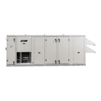
Phase Monitor
The unit control circuitry includes
a phase monitor that constantly
checks for phase reversal, phase
imbalance, loss of phase or
a power brownout. It requires
24 VAC to operate and when it
detects a fault, it cuts off the 24
VAC that goes to the low voltage
terminal strip, thereby shutting off
all motors.
Component Operation
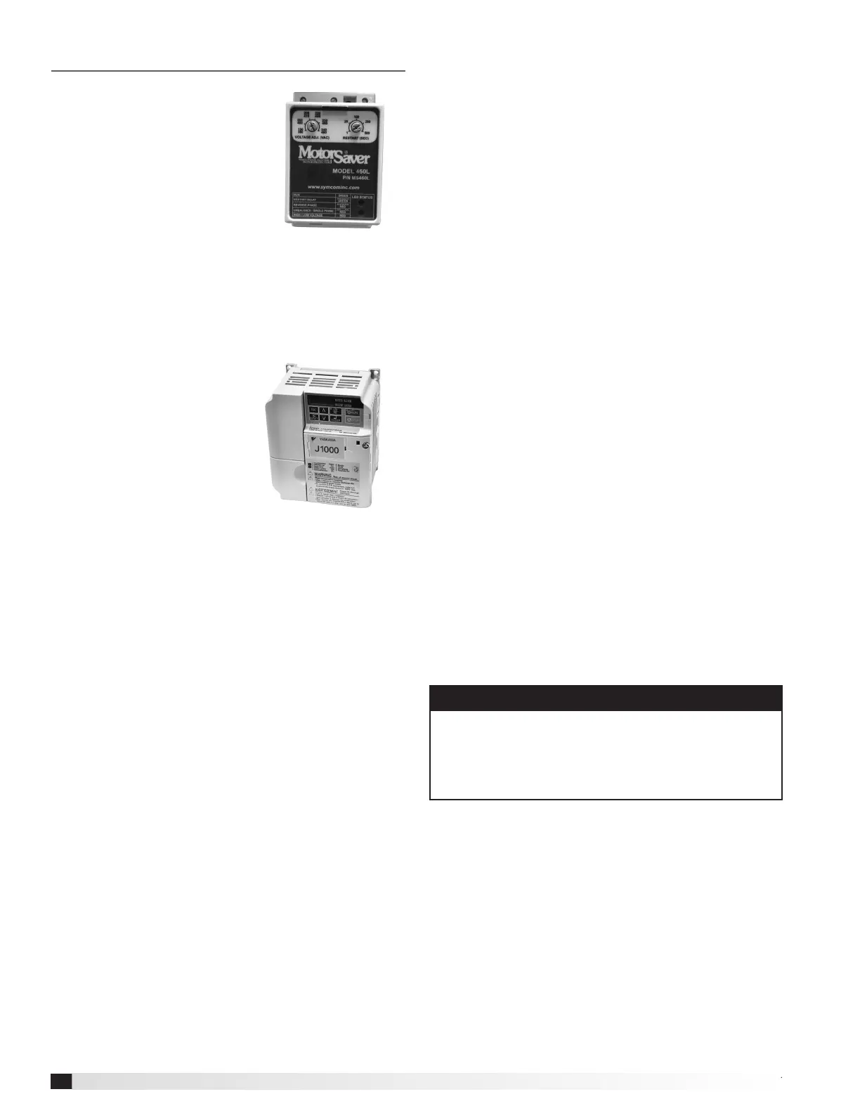
Variable Frequency Drive (VFD)
If a VFD was provided and installed at the factory, it has
been pre-set to control the speed of the blower motor
for optimum performance. The motor speed needs to
be veried during test and
balance of the unit.
If the system was congured
for Constant Air Volume
(CAV), the VFD will operate
in an ON / OFF fashion and
the speed of the motor will
not change. If the system
was congured for Variable
Air Volume (VAV), the
microprocessor controller will
constantly monitor operating
conditions and provide a signal to the VFD, changing the
VFD output as needed.
The VFD may alternatively be connected to an external
signal such as provided by a BMS and be operated by a
2 - 10 VDC or a 4-20 mA input.
Supply Fan VFD Sequence
Optional Room CO2 Sensor: The microprocessor
controller will modulate the supply fan based on a
comparison of the CO2 setpoint to the actual CO2
levels reported from the sensor. Mechanical high static
protection cutoffs must be installed by others to protect
the system and equipment from over-pressurization.
Typical Variable
Frequency Drive (VFD)
Typical Phase Monitor
Optional Exhaust Fan Only Power
The exhaust fan will have a dedicated power circuit
where in the case of a power outage, the exhaust fan will
still run. A phase monitor will detect an outage or power
loss and open the contact, disconnecting all power to the
unit and controller. An external signal will need to be sent
to a relay to power the exhaust fan, enabling the fan to
run at a maximum speed. This sequence is NOT to be
used for high temperature exhaust applications.
Airow Monitor
A factory-wired, mounted, and powered airow
monitoring system is provided in the outdoor and/or
exhaust air streams. The airow control system offers
the following functionality:
• Display of outdoor and/or exhaust airow rate in actual
cubic feet per minute (CFM) or actual liters per second
(LPS) on a 16 character LCD display.
• Two congurable analog outputs for transmitting
outdoor and/or exhaust airow rate, outdoor air
temperature, or a proportional-integral-derivative (PID)
control signal based on an outdoor airow set point.
• A congurable digital output that operates based on an
airow set point or range.
Operation
Outdoor and/or exhaust airow monitoring is
accomplished using two thermal dispersion sensors
that accurately measure airow velocity down to zero
feet per minute (fpm). The airow controller takes the
average measurement for two sensor congurations,
and determines the outdoor airow rate based on the
effective intake area. Field calibration of the outdoor
airow monitoring device determines the effective intake
area of the unit.
Refer to GreenTrol® Automation Inc. GF-2200A and
GF-N2211technical data sheet for further detail.
Important
For the airflow monitoring device to perform as
intended, field calibration is required. Calibration of
the airflow monitoring device requires an independent
measurement of airflow and should be performed
when the system undergoes test and balance.
© 2017 Mitsubishi Electric US, Inc.