47
Packaged and Split Rooftop Ventilator
© 2021 Mitsubishi Electric US, Inc.
LEV
The valve opening changes according to the number of pulses.
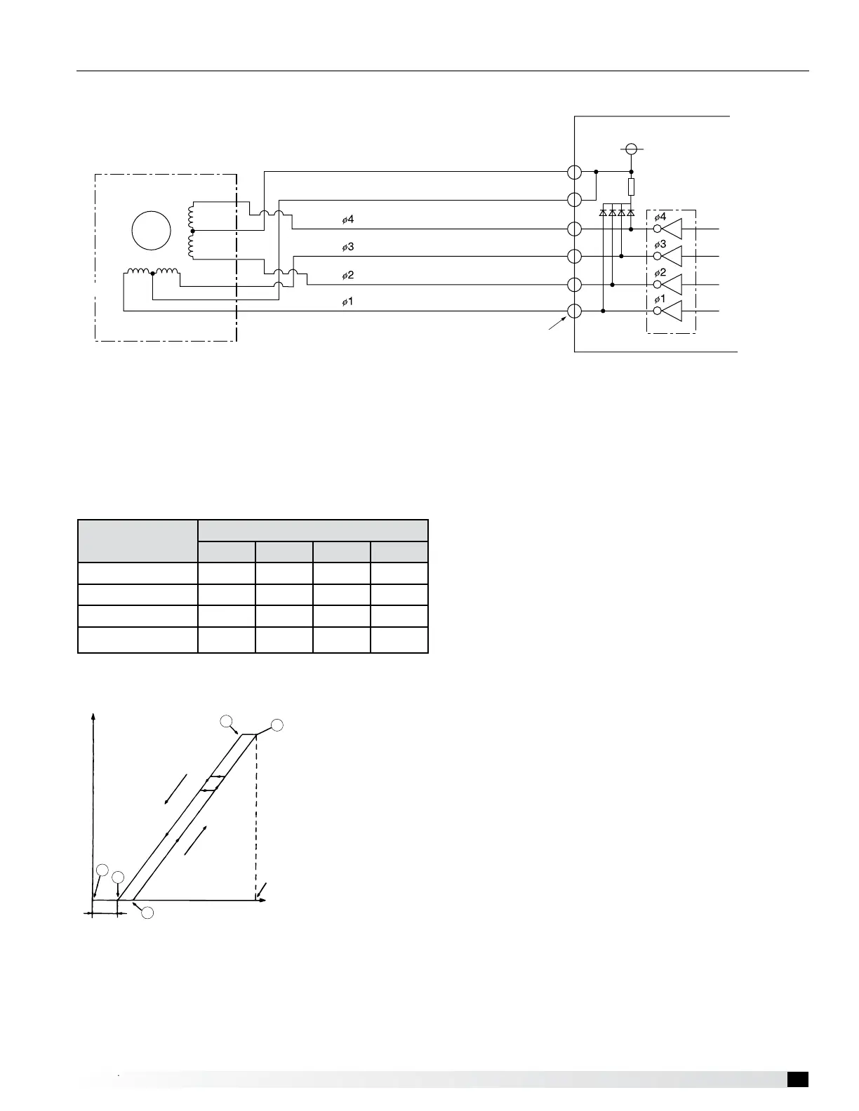
1- AHU controller board and LEV Connection.
4
3
6
5
2
1
(H)
(I)
(J)
(A)
(A)
(B)
(B)
(C)
(C)
(D)
(D)
(E)
(E)
(F)
(F)
12VDC
M
4
6
2
3
5
1
(A) Brown (F) White
(B) Red (G) Control board
(C) Blue (H) Connection (CN60, CNLE V2)
(D) Orange (I) Drive circuit
(E) Yellow (J) Linear expansion valve
2- Pulse Signal Output and Valve Operation
Output (phase)
number
Output State
1 2 3 4
ø1
ON OFF OFF ON
ø2
ON ON OFF OFF
ø3
OFF ON ON OFF
ø4
OFF OFF ON ON
Output pulses change in the following orders when the
Valve is closed: 1 →2 →3 →4 →1
Valve is open: 4 →3 →2 →1 →4
*1. When the LEV opening angle does not change, all
the output phases will be o.
*2. When the output is open phase or remains ON, the
motor cannot run smoothly, and rattle and vibrates.
3- LEV Valve Closing and Opening Operations
Valve opening (refrigerant flow rate)
Valve closed
Valve open
E
B
Pulses
Fully open: 1400 pulses
A
C
* When the power is turned on, the valve closing signal
of 2200 pulses will be output from the inboard to LEV to
x the valve position. It must be xed at Point A.
When the valve operates smoothly, no sound from LEV
or no vibration occurs, however, when the pulses change
from E to A in the chart of the valve is locked, a big
sound occurs.
* Whether a sound is generated or not can be
determined by holding a screwdriver against it, then
placing your ear against the handle.
Troubleshooting – Split DX Refrigeration Circuit