CONTROLS & CONNECTIONS
12
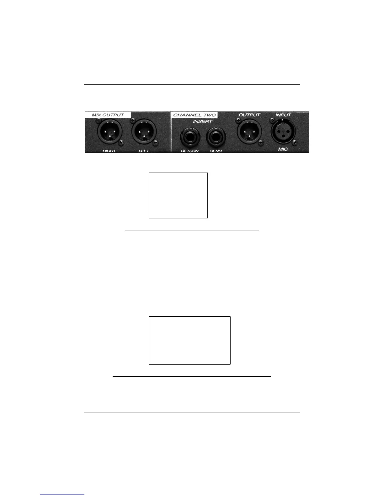
2.4 BACK PANEL BASIC LAYOUT
PIN 1 GND
PIN 2 High (+)
PIN 3 Low (-)
Cable Wiring Diagram for Input and Output XLR
The Output XLR Connector is servo balanced and operates at +4dBu.
The Return / Line In connector of the MP20 is provided for use in
conjunction with audio process devices such as compressor/limiters and as a
Line In for recording media such as tape machines, hard disc recorders, or
DAT’s. When a device is connected to this jack, the Neutrik? Combo jack is
disconnected.
TIP High (+)
RING Low (-)
SLEEVE GND
Cable Wiring Diagram for Balanced Send / Return Jacks
The Send Jack on the back panel of the MP20 routes the signal being
processed by the channel to outboard devices or to recording media.