30
www.pridemobility.com Go-Go Ultra
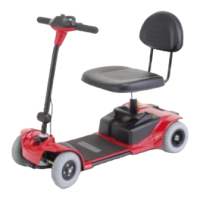
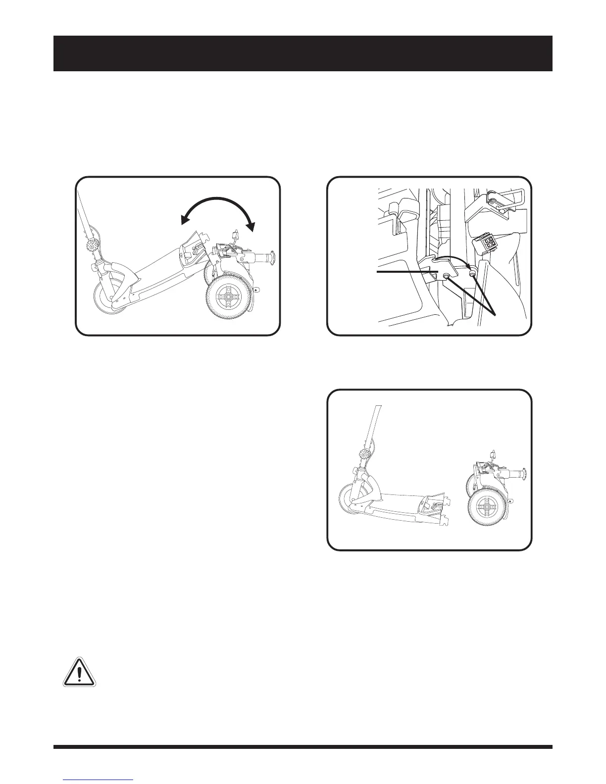
Figure 18. Frame Sections
VIII. DISASSEMBLY AND ASSEMBLY
Frame Separation
1. Push back on the seat post to pivot the scooters rear section rearward until the rear section is standing
vertically on its bumper. See figure 16.
2. Lift the front section up until the lower pegs are no longer in the curved locking brackets. See figure 17.
3. Carefully lift the front section away from the rear section. See figure 18.
ASSEMBLY
1. Position the front and rear sections of your scooter as shown
in figure 18.
2. Holding the seat post, slowly pivot the rear section for-
ward until the curved locking brackets are fully con-
nected onto the top rear pegs. See figure 16 and 17.
3. Loosen the tiller adjustment knob, raise the tiller, then
retighten the tiller adjustment knob.
4. Secure the toggle latch. See figure 15.
n Lower the toggle latch buckle.
n Push the toggle latch so it locks into place.
5. Connect the front-to-rear harness.
6. Reinstall the battery pack by lowering it straight down
until it is securely in place.
7. Replace the seat and rotate it until it locks into its cor-
rect position.
8. Unlock the front wheel by turning the tiller lock knob
90° anticlockwise. See figure 12.
WARNING! After assembling the
scooter, make absolutely certain the
tiller lock knob is in the unlocked
position before attempting to ride your
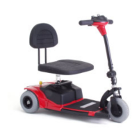
Figure 16. Frame Positioning
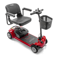
PEGS
CURVED
LOCKING
BRACKET
Figure 17. Frame Lockup
scooter.
 Loading...