Jazzy 600 www.pridemobility.com 27
VI. COMFORT ADJUSTMENTS
two states: clamped and unclamped. When the lever is open,
the quick release fastener is unclamped. When the lever is
closed, the quick release fastener is clamped.
To clamp the quick release fastener:
1. Make sure the lever is in the open position.
2. Turn the nut clockwise until it is snug.
3. Rotate the lever until it is in the fully closed position.
NOTE: If the lever will not rotate to the fully closed
position, then turn the nut counterclockwise one-quar-
ter or one-half turn.
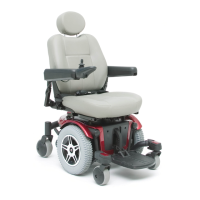
Foot Platform Angle
You can adjust the angle of the foot platform with a hex key.
See figure 15.
To adjust the foot platform angle:
1. Flip up the foot platform and locate the setscrew.
2. Turn the setscrew counterclockwise to raise the front of
the foot platform.
3. Turn the setscrew clockwise to lower the front of the
foot platform.
Controller Position
You can position the controller for either left-hand or right-
hand use.
WARNING! Do not place the controller
cable so that it can be pinched in the
seat frame or the power base frame.
To change the controller position:
1. Turn the rear shroud fasteners one-quarter turn. See
figure 6.
2. Remove the rear shroud.
3. Unplug the controller connector(s) from the power base.
4. Cut the wire tie(s) securing the controller cable to the
armrest.
5. Flip up the armrest and loosen the setscrew. See figure 17.
6. Slide the controller out of the armrest.
7. Loosen the setscrew in the other armrest.
8. Place the controller in the other armrest.
9. Tighten the setscrew to secure the controller.
10. Use a wire tie to secure the controller cable to the armrest.
11. Plug the controller connector(s) into the power base.
12. Reinstall the rear shroud and tighten the fasteners.
Figure 17. Underside of Armrest
SETSCREW
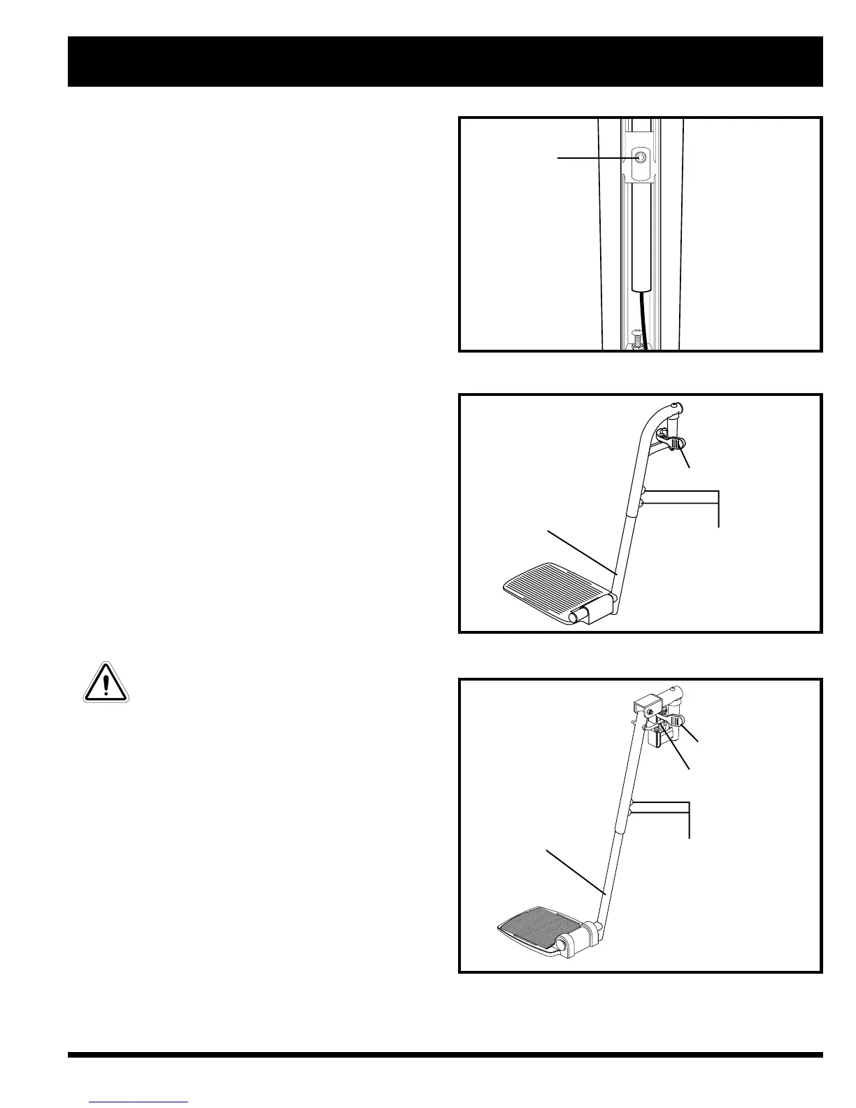
Figure 18. Swing-Away Footrests
FOOTREST
ADJUSTMENT
SCREWS
FOOTREST
EXTENSION
SFR RELEASE LEVER
LEG REST
ADJUSTMENT
SCREWS
RELEASE LEVER B
Figure 19. Elevating Leg Rests
RELEASE LEVER A
LEG REST
EXTENSION