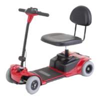
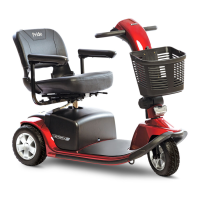
Jazzy Select GT www.pridemobility.com 35
Battery Replacement
A battery wiring diagram is printed on a decal located on the power base. See VI. “Batteries and Charging” for
correct battery specifications.
MANDATORY! Battery posts, terminals, and related accessories contain lead and
lead compounds. Wear goggles and gloves when handling batteries and wash hands
after handling.
WARNING! The batteries in your power chair should only be serviced or replaced by
an authorized Pride Provider or a qualified technician.
WARNING! Do not replace batteries when seat is occupied.
WARNING! Power chair batteries are heavy. See specifications table. If you are
unable to lift that much weight, be sure to get help. Use proper lifting techniques and
avoid lifting beyond your capacity.
WARNING! Do not mix old and new batteries. Always replace both batteries at the
same time.
To replace the batteries:
1. Turn off the power to the controller.
2. Make sure that the power chair is in drive mode. See figure 8.
3. Remove the seat.
4. Remove the rear shroud. See figure 21.
5. Loosen the yellow thumbscrews and remove the side cover.
6. Disconnect the rear battery cable from the rear battery terminals. See figure 21.
7. Slide the rear battery out of the power base.
8. Slide the front battery rearward.
9. Disconnect the front battery cable from the front battery terminals. See figure 21.
10. Slide the front battery out of the power base.
11. Install the front battery cable onto the new battery terminals. Make sure that the hardware is facing the correct
direction. See figure 21.
WARNING! Make sure you tighten the fasteners so that the connections are secure.
12. Place the front battery into the power base. Make sure that the terminals are facing the front of the power base.
See figure 21.
13. Slide the front battery forward.
14. Install the rear battery cable onto the new battery terminals. Make sure that the hardware is facing the correct
direction. See figure 21.
15. Place the rear battery onto the power base. Make sure that the terminals are facing the front of the power base.
See figure 21.
16. Reinstall the side cover.
17. Reinstall the rear shroud.
NOTE: When installing the rear shroud, make sure that the controller harness is routed through the notch in
the right side of the front cover.
18. Charge the batteries. See VI. “Batteries and Charging.”
VII. CARE AND MAINTENANCE