Do you have a question about the Pride Amp Series and is the answer not in the manual?
Critical safety warnings regarding high voltages and cover removal.
Lethal voltages, interlock hazards, and operational risks.
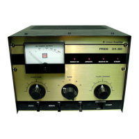
General description of the Pride DX-300 linear amplifier.
Details on power ratings, frequency coverage, and device complement.
Steps for connecting and grounding the amplifier for operation.
Detailed instructions for tuning and operating the amplifier.
Overview of the DX-300's high gain, single tube design.
Description of the high voltage rectifier and filter circuit.
Description of the screen and bias voltage generation circuits.
Description of the low voltage supply for auxiliary functions.
Description of input matching, switching, and control circuitry.
Explanation of the safety interlock mechanism.
Description of the internal wattmeter circuit.
Procedure for measuring plate current via the metering jack.
Steps for adjusting the tube's bias voltage.
Procedure for calibrating the front panel wattmeter.
Procedure for adjusting input SWR on specific bands.
Guide for checking critical voltages within the unit.
Routine checks and recommended maintenance procedures.
Instructions and considerations for replacing the transmitting tube.
Component layout diagram for the low voltage supply board.
Component layout diagram for HV Supply Board #1.
Component layout diagram for HV Supply Board #2.
Component layout diagram for the wattmeter board.
Component layout diagram for the RF input/control board.
Component layout diagram for the safety interlock PCB.
Trace layouts for power supply and RF control PCBs.
Physical layout of front panel controls and rear panel connections.
Internal physical layout of major components.
List of components for HV Power Supply #1.
List of components for HV Power Supply #2.
List of components for the safety interlock circuit.
List of components for the low voltage supply.
List of components for the RF input and control board.
List of components for the wattmeter PCB.
List of various chassis-mounted parts and switches.
General advice and warnings for performing circuit modifications.
Modification to improve the reliability of the screen LED.
Discussion on improving screen supply regulation.
Method to stop tube oscillation with an added capacitor.
Modification for the wattmeter PCB output coax connection.
Nomad Radio mod for bias circuit using zeners.
Alternative bias modification using a transistor and zener.
Introduction to details on various components used.
Details on antenna change over and preamp relays.
Cautionary notes regarding the band switch operation.
Specifications for input transformer and coils.
Details on the Z1 grid parasitic suppressor.
Details on the Z2 parasitic suppressor and related resistors.
Information regarding the unit's cooling blower.
List of recommended suppliers for replacement parts.