32
Copyright © 2004 CBTricks.com
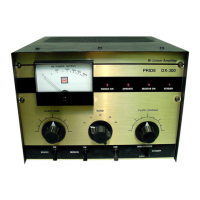
Pride DX300 CHAPTER 7
Circuit Modifications
7.0 Introduction
NOTE:
Exercise a great deal of care with any Modifications done
Due to the high Voltage, and close proximity of the surrounding components.
If done wrong you could destroy components / or KILL yourself.
If you have even the slightest doubts or the proper equipment, it would be wise to have someone else
you trust perform the mod for you.
SO TAKE YOUR TIME AND DOUBLE CHECK YOUR WORK!!!!
7.1 Screen LED Modification
The 'Screen' LED (LED4) seldom lasts long, but we use a 2W part for R35 and R36, same resistance values.
The LED will still die if there's a surge on the screen, but the larger resistors take it better than the stock 1/2W
parts.
7.2 Screen Supply Modification
The Pride DX300 has no screen regulation and should, Nomad Radio (http://www.nomadradio.com) is working
on a new Low Voltage PCB. I have seen Prides with a 25K 10W to ground on the +350v supply.
A person could build a regulator for the supply. So check his web site for details.
7.3 Tube Oscillation
Adding another capacitor on the B+ side of the plate choke can stop oscillation of the tube.
Typically .001µF at 3000Volts
7.4 Wattmeter PCB Modification (Nomad Radio Mod)
On the small circuit board bolted to the rear of the meter, the output coax should be SOLDERED DIRECTLY TO
THE BOARD. First unplug the two coax cables from it. Loosen the nuts on the meter posts, and GENTLY pull
the board away from the meter body.
You will need to unsolder the bare ground wire from the inboard-lower corner.
Heat the solder to the four pins where the two coaxes were plugged in, and pull them completely out of their
holes. You will need to ream the two ground holes (the ones on the outside edge) out to a hole size of about
3/32 of an inch. You also need to clear any leftover solder from the two holes where the coax center wires attach.
Remove the spring contacts from both the coax cables that you unplugged from the meter board. Strip about 3/8
of an inch from the end of each. You should also pull off the shrink tubing that covers the coax braid. Tin each of
these wire ends to hold all those loose strands together. Now insert the tinned wire ends back into the four holes
in the meter board. Solder them in place, and that skinny bare ground wire on the corner of the board. When the
meter board is mounted back onto the meter posts.