32
Copyright © 2004 CBTricks.com
Pride DX-300 CHAPTER 2
2.0 INSTALLATION:
1) Select a location for your amplifier. RF amplifiers need ventilation, so choose a location that will not restrict the
air flow around the amp and where it won’t get water, coffee, or soft drinks spilled on or in it.
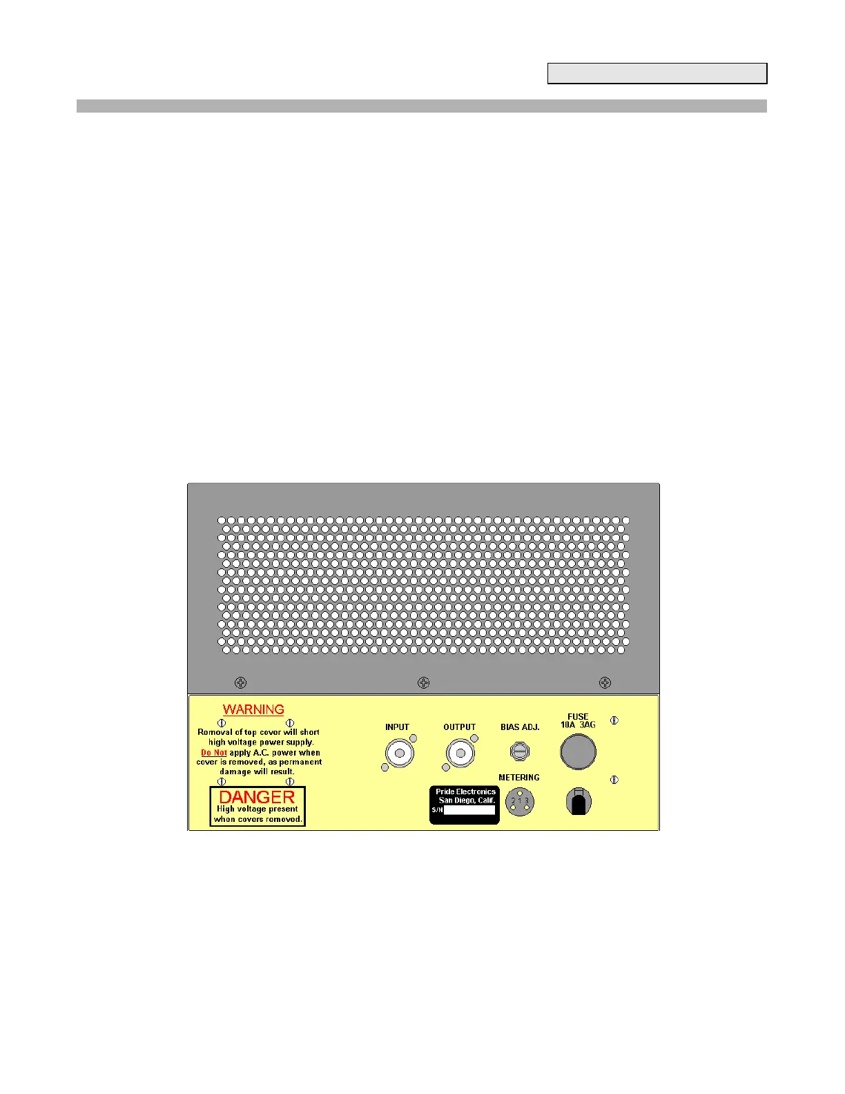
2) Connect a short length of coaxial cable from the exciter to the amplifier input connector. RG58/U or RG8/U
may be used and a PL 259 connector is required at the amplifier end of the cable. This cable should be as short
as is practical, preferable less than five feet.
3) Connect antenna or suitable high power dummy load to the output connector of the amplifier using RG8/U
coax. The smaller RG58/U coax may be used with matched antenna systems (better than 1.5 to 1 SWR) but will
have somewhat higher loss. The amplifier will match most loads from 25 to 100ohm.
4) Exciter power levels above 12 watts PEP or 5 watts carrier level should be avoided as over drive of the
amplifier will occur.
5) The unit should be grounded for R.F. by attaching a ground strap of coaxial shield or 10-12 gauge wire to the
ground post on the amplifier. This should be connected by a short run to a ground rod or cold water pipe. The
idea is to have a short direct earth ground to keep the chassis at radio frequency ground. In many cases normal
operation can be had without such a ground, but a good ground can help prevent television interference, and
make tuning straightforward.
6) The A.C. line cord should be plugged into a three-wire outlet. The electrical circuit should be capable of
handling a 10-ampere load.
Figure 2-0 Rear Panel