Jazzy 1107 www.pridemobility.com 19
III. YOUR POWER CHAIR
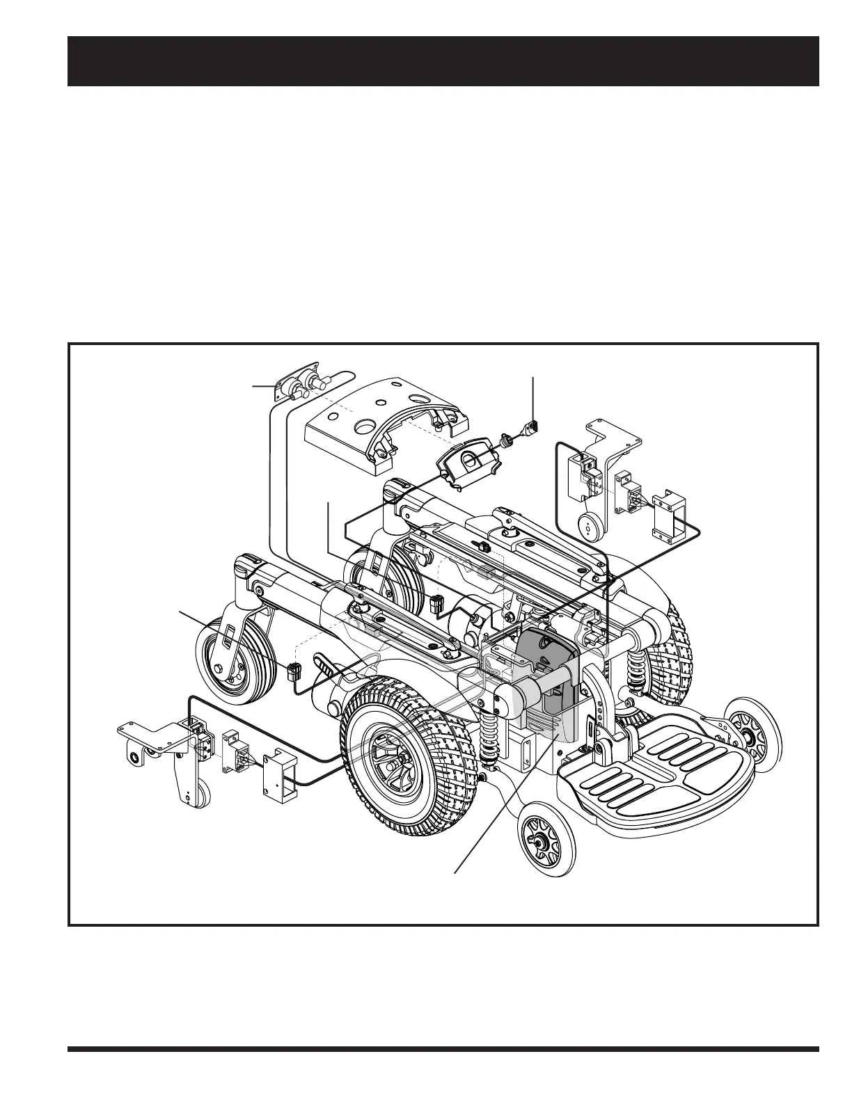
Figure 7. Jazzy 1107 Electrical Components (FLIGHT Controller Shown)
BATTERY HARNESS CONNECTOR
CONTROLLER HARNESS CONNECTOR
MOTOR
CONNECTOR
MOTOR CONNECTOR
CONTROLLER POWER MODULE
Motor Connectors: This is where the motors connect to the controller power module.
Main Circuit Breaker (located on rear battery box): The main circuit breaker is a safety feature built into your power
chair. When the batteries and the motors are heavily strained (e.g., from excessive loads), the main circuit breaker trips to
prevent damage to the motors and the electronics. If the circuit trips, allow your power chair to “rest” for approximately
one minute. Next, push in the circuit breaker button, turn on the controller, and continue normal operation. If the main
circuit breaker continues to trip repeatedly, contact your authorised Pride Dealer.
Controller Power Module: The controller power module enables the controller to communicate with the batteries and
the motors.