SC7132 9
EN
II. YOUR SCOOTER
Battery Condition Meter
When the key is fully inserted and turned clockwise to power up your scooter, this meter indicates the approximate
battery voltage strength. For further information on battery charging, see III. “Batteries and Charging.”
Status LED
The status LED alerts you to electrical problems that may occur with the scooter. The LED remains constantly lit
while your scooter is on. If your scooter develops an electrical problem, the status LED will fl ash a code. See VII.
“Basic Troubleshooting” for fl ash codes.
Key Switch
Insert the key into the key switch and turn it clockwise to power up (turn on) your scooter.
Turn the key counterclockwise to power down (turn off ) your scooter.
WARNING! When faced with an emergency situation, switch off the key to power off the scooter.
Use caution. Be advised that turning off power to the scooter may cause the scooter to stop
abruptly. To release the emergency stop and restore driving capability to the scooter, release
the throttle control lever and then switch on the key to the scooter.
WARNING! If the key is turned to the “off” position while your scooter is in motion, the electronic
brakes will engage and your scooter will come to an abrupt stop.
Mirror Positioning and Adjustment
For information on positioning and adjusting your mirror, see V. “Comfort Adjustments.”
Tiller Angle Adjustment
For information on positioning and adjusting your tiller, see V. “Comfort Adjustments.”
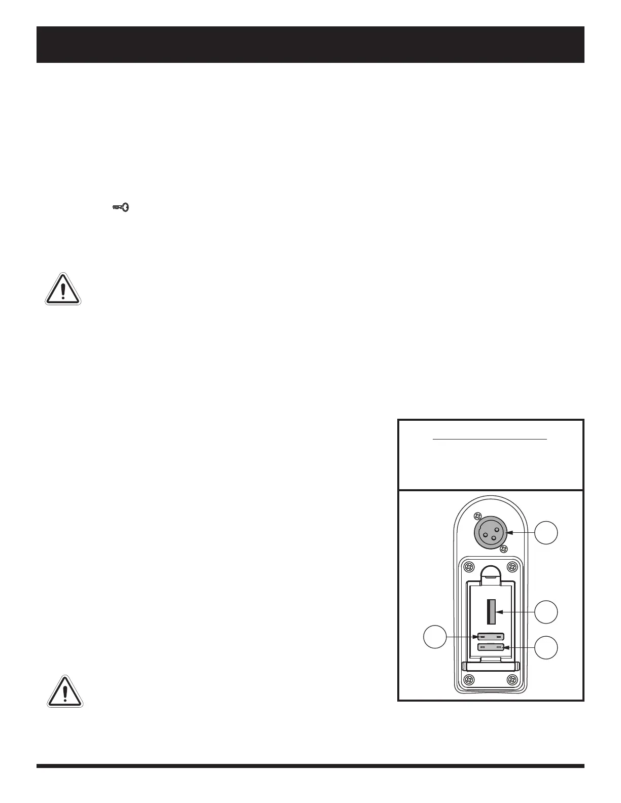
Off-board Charger Port
The off -board charger power cord plugs into this port during battery
charging. The off -board charger port is located on the tiller. See fi gure 2.
Electrical System Fuses
Your scooter is equipped with a series of electrical system fuses, which
help protect the off -board charging system, key switch and lighting system
from receiving an overload of electrical current. These fuses are the same
type used in automobiles and are located in a compartment on the tiller.
See fi gure 2. See VII. “Care and Maintenance” for fuse replacement.
NOTE: Keep all electrical areas clean and free of moisture and
foreign material.
Handbrake Lever
This lever provides you with supplemental stopping power. When in
motion, release the throttle control lever and gently squeeze the handbrake
lever to come to a stop. Handbrake eff ectiveness can be modifi ed by
tightening or loosening the setscrew located on the handbrake lever.
WARNING! The handbrake is intended for use as a
supplemental braking.
IDENTIFICATION KEY
1. OFF-BOARD CHARGER PORT
2. USB PORT
3. KEY FUSE
4. BATTERY FUSE
1
2
4
3
Figure 2. Off-board Charger Port/Tiller
Console Fuses