
J
Jack AllenAug 2, 2025
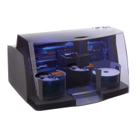
Why does the picker repeatedly drop but not grab discs in my Primera Bravo 4202?
- EEvelyn NolanAug 3, 2025
If the picker drops down onto discs in bins multiple times but doesn't grab a disc, the solenoid might be the problem.
Why does the picker repeatedly drop but not grab discs in my Primera Bravo 4202?
If the picker drops down onto discs in bins multiple times but doesn't grab a disc, the solenoid might be the problem.
What causes the picker to not place discs in the print tray on my Primera Bravo 4202?
If the picker grabs a disc but doesn't place it in the print tray and moves to the home position, the arm board or sensor flag bracket might be the problem.
Why isn't the solenoid clicking on my Primera Bravo 4202 Disc Duplicator?
If the solenoid does not click, but the carrier, print tray, and picker are moving, the solenoid itself might be the problem.
Loosen the four screws located on the back of the printer's cover.
Remove three screws from the front cover and slide the picker and carrier to the printer's center.
Unplug the control panel cable and the blue LED board cable from the mainboard before removing the cover.
Remove three screws securing the control panel and test button functionality after replacement.
Remove two screws securing the blue LED board and unplug its cable from the board.
Remove two screws securing the cover plate and then remove the plate itself.
Unplug SATA cables from the hub and remove three screws securing the hub.
Ensure hub pins properly connect to mainboard connectors and reconnect SATA cables.
Unplug all cables and flex cables from the mainboard after removing the USB3 hub.
Remove four screws securing the mainboard and lift it out of the unit.
Remove two screws and three standoffs from the static brush and transfer them to the new mainboard.
Ensure mainboard aligns with the post, reconnect cables, USB3 hub, and motors.
Remove two screws securing the print tray guide to the print tray and lift the guide off.
Lift the back end of the print tray slightly and pull it back against the rear cover plate.
Remove the screw securing the front tray guide and lift the guide out of its base.
Pull the print tray completely out of the printer.
Cut the tie wrap securing the power resistor cable and unplug it from the mainboard.
Remove two screws securing the resistor mount bracket to the rear cover plate.
Remove two screws securing the power resistor to its mount bracket and replace the resistor.
Cut the tie wrap securing cables and unplug the encoder wheel sensor from the mainboard.
Remove the two screws that secure the sensor to its bracket.
Ensure the encoder wheel is centered within its slot when replacing the sensor.
Peel the encoder wheel off its gear and clean the area with alcohol before applying a new wheel.
Ensure the new encoder wheel is centered in the sensor slot and clean it after handling.
Tip the printer up and remove the six screws securing the drive mount base plate to the base.
Tip the drive mount forward, align its slot with the rear cover plate tab, and remove it.
Unplug all cables from the back of the drive(s) to detach the drive mount from the printer.
Remove the drive mount, unplug the power supply from the mainboard, and cut securing tie wraps.
Remove the five screws securing the power supply to the rear cover plate.
Lift the power supply out of the printer and pull its power cable through the bottom opening.
Route the drive power cable to the underside of the printer, ensuring it's not pinched.
Remove the drive mount, cut tie wraps, and unplug the drive fan from the mainboard.
Remove the two screws securing the fan to the inside of the rear cover plate.
| Brand | Primera |
|---|---|
| Model | Bravo 4202 |
| Category | Disc Duplicator |
| Language | English |