10
4—INSTALLATION
4.3– TERMINAL BOX
The equipment must be connected with an equi-potential system . the connection terminal is located
near the terminal box. The bonding wire must have a minimal section of 10 mm ².
4.4– EQUIPOTENTIAL
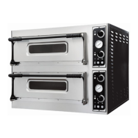
The terminal box is placed externally on the back of the oven.
SINGLE
PHASE
yellow/green
yellow/green
blue
blue
brown
brown
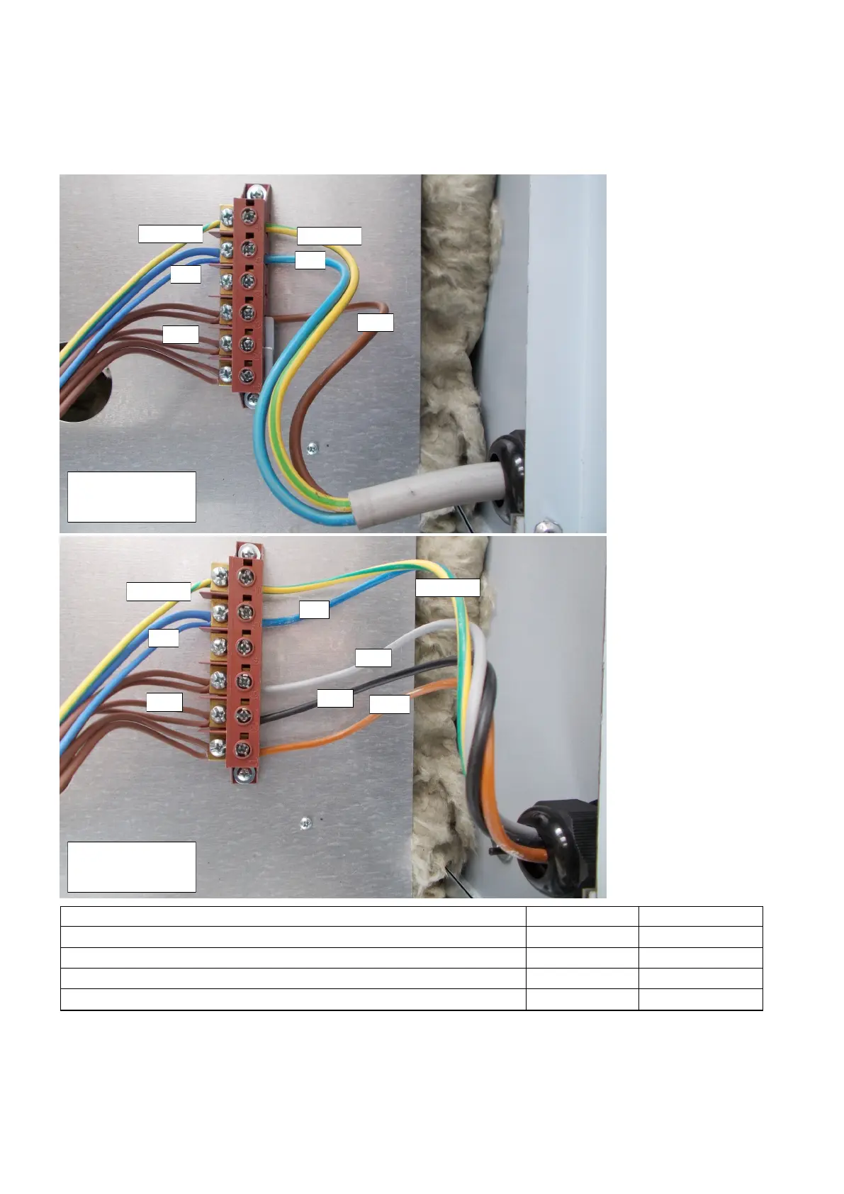
THREE PHA-
SE
blue
yellow/green
yellow/green
blue
grey
black
brown
brown
Oven type N. of cables Section (mm²)
Single phase, one chamber 3 4
Single phase, two chambers and versions 9 single phase 3 6
Three phase one chamber and two chambers 5 4
Three phase from versions 9 and up 5 6
PIC. A
PIC. B