EasyManuals Logo

Pro-face GP-4503T User Manual

Pro-face GP-4503T
241 pages
To Next Page IconTo Next Page
To Previous Page IconTo Previous Page
Page #220 background imageLoading...
Page #220 background image
220
7.7 Installation
Installation Method
Panel type: Weld the stud bolts to the panel, and then tighten the nuts to fasten the
GP unit to the panel.
Resin boss type: Tighten the screws to attach the GP unit to the bosses of the resin
boss-molded product.
Standard mount: The GP unit's screen is fixed within the inside of the panel or resin
boss-molded product.
Flat mount: The GP unit's screen is fixed to the same surface of the panel or resin
boss-molded product.
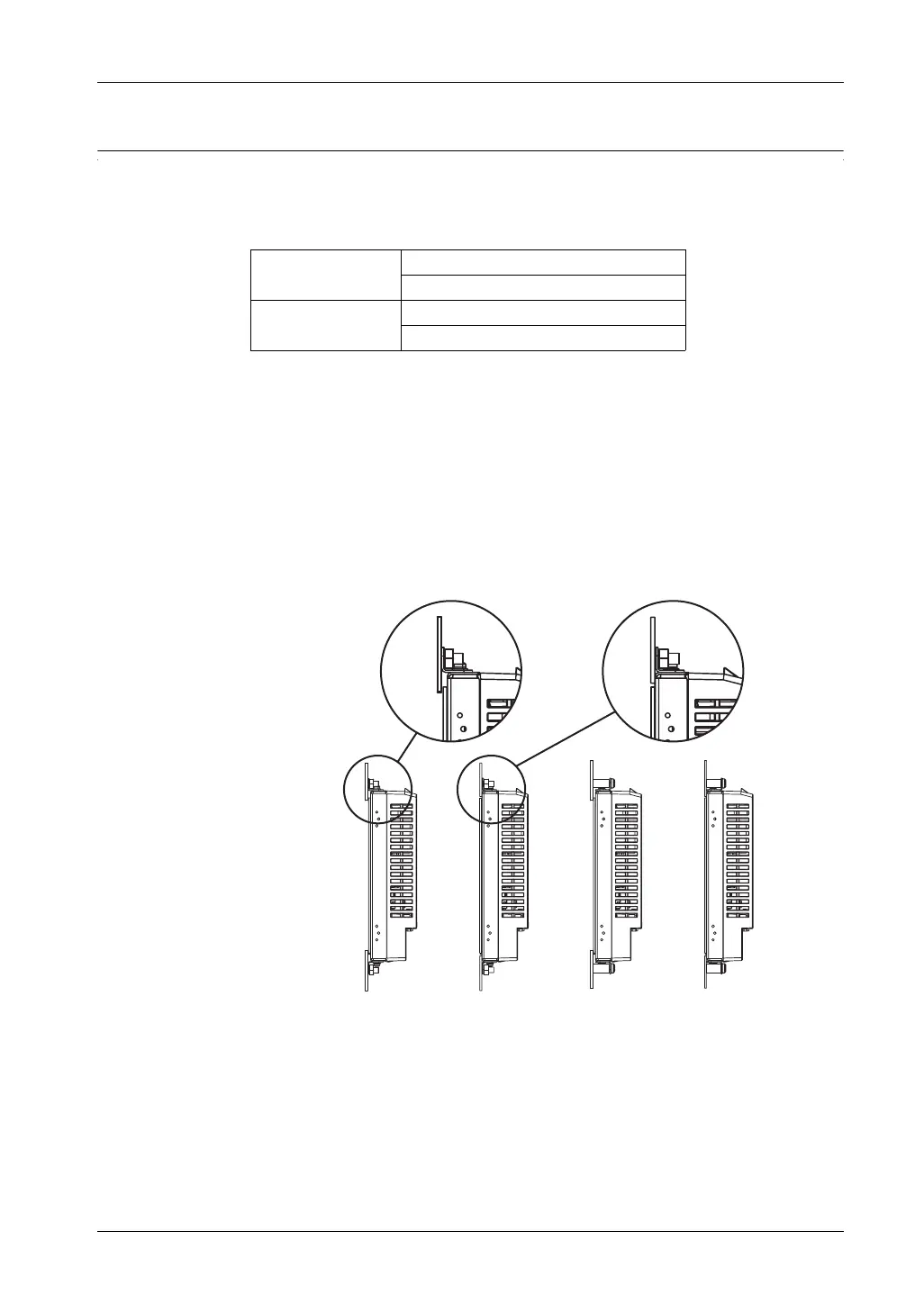
Installation diagrams (profile)
1) Panel type, standard mount
2) Panel type, flat mount
3) Resin boss type, standard mount
4) Resin boss type, flat mount
As shown in the figures, installation brackets can be attached at the top and bottom
surfaces of the GP unit or on either side of the GP unit.
Panel type standard mount
flat mount
Resin boss type standard mount
flat mount
(1) (2) (3) (4)

Table of Contents

Questions and Answers:

Question and Answer IconNeed help?

Do you have a question about the Pro-face GP-4503T and is the answer not in the manual?

Pro-face GP-4503T Specifications

General IconGeneral
Display TypeTFT Color LCD
Touch TypeAnalog Resistive
Power Supply24 VDC
BacklightLED
Touch Panel Resolution1024 x 1024
SD Card SlotYes
Display Size10.4 inches
Resolution800 x 600 pixels
Operating Temperature0 to 50 °C
Communication PortsRS-232, RS-422, RS-485
Colors65, 536 colors
Ethernet10/100BASE-T
USBUSB 2.0
Storage Temperature-20 to 60 °C
Relative Humidity10% to 90% (non-condensing)
Weight3.5 kg
Serial InterfaceRS-232C, RS-422/485

Related product manuals