GP4000 Series Hardware Manual
145
GP-4500 Series / GP-4600 Series
NOTE: The DC power supply connector (plug) for GP-4200 Series / GP-4300 Series
/ GP-4400 Series is PFXZCBCNDC1 (manufactured by Pro-face).
The DC power supply connector (plug) for GP-4500 Series / GP-4600 Series is
PFXZCBCNDC2 (manufactured by Pro-face).
(The above items are manufactured by Phoenix Contact.)
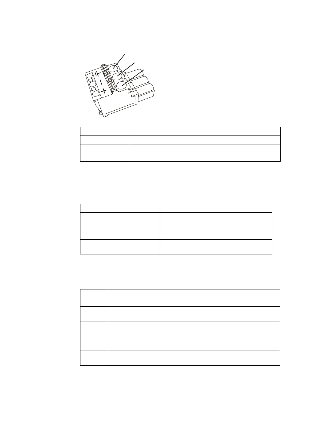
How to connect the DC Power Cord
Connection Wire
+ 24 Vdc
-0 Vdc
FG Grounded terminal connected to the panel chassis.
Recommended Driver SZS 0.6x3.5 (1205053)
Recommended Pin Terminals 3201288 AI 0,75-10 GY
3200182 AI 1 -10 RD
3200195 AI 1,5 -10 BK
3202533 AI 2,5 -10 BU
Recommended Pin Terminal Crimp
Tool
CRIMPFOX 6
FG
-
+
Step Action
1 Confirm the power cord is not connected to the power supply.
2 Check the rated voltage and remove the “DC24V” sticker on the DC power
supply connector.
3 Remove 10 mm (0.39 in.) of the vinyl membrane off the ends of the power cord
wires.
4 If using stranded wire, twist the ends. Tinning the ends with solder reduces risk
of fraying and ensures good electrical transfer.
5 Push the Opening button with a small and flat screwdriver to open the desired
pin hole.
 Loading...