Installation and Wiring
146
NOTE:
z Do not solder the wire directly to the power receptacle pin.
z To prevent the possibility of a terminal short, use a pin terminal that has an
insulating sleeve.
z You can connect the DC power supply connector for GP-4200 Series, GP-4300
Series, or GP-4400 Series to GP-4500 Series or GP-4600 Series units. However,
the reverse is not possible. You cannot connect the DC power supply connector
for GP-4500 Series or GP-4600 Series to GP-4200 Series, GP-4300 Series, or
GP-4400 Series units.
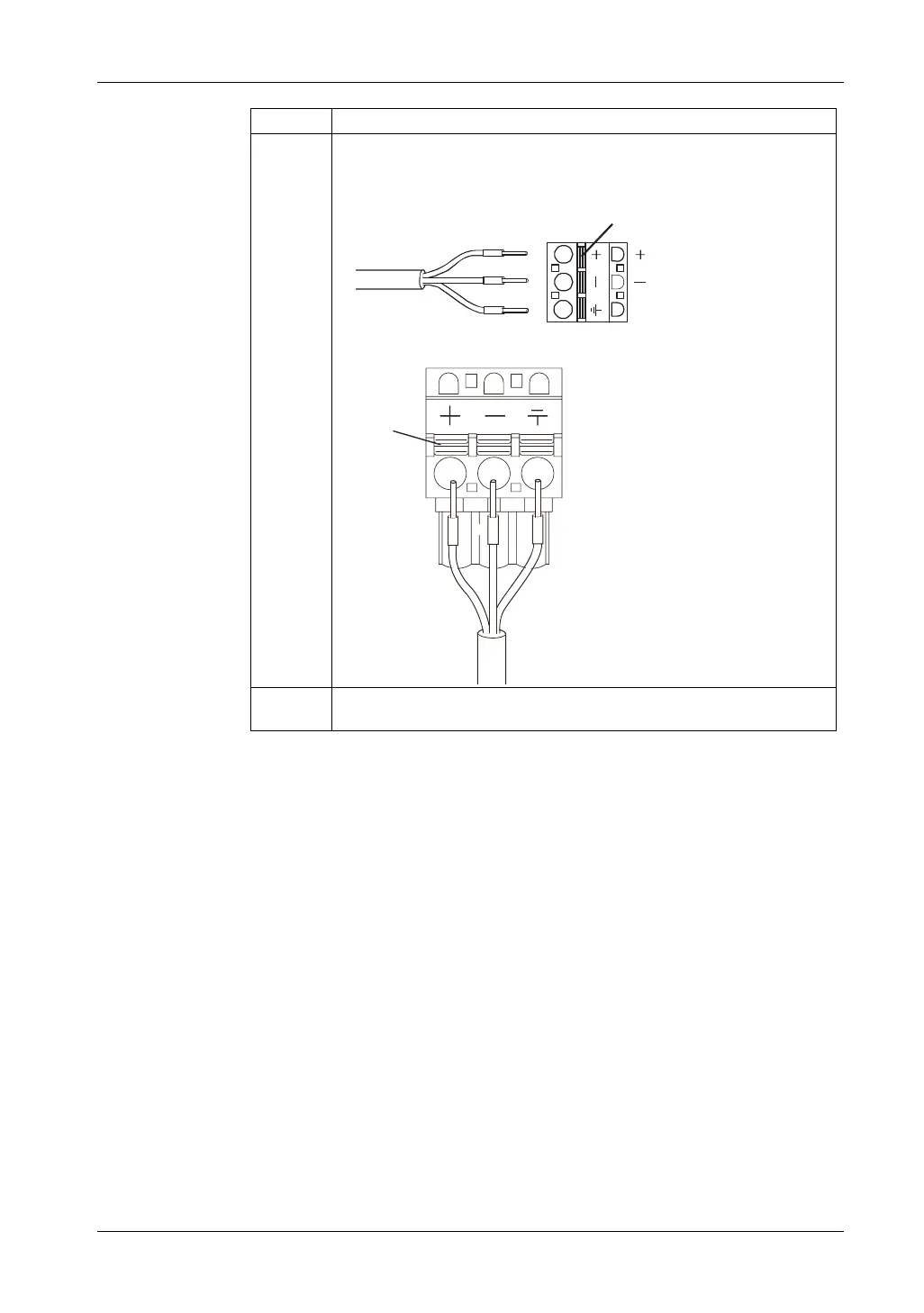
6 Insert each pin terminal into its corresponding hole. Release the Opening
button to clamp the pin in place.
GP-4200 Series / GP-4300 Series / GP-4400 Series
GP-4500 Series / GP-4600 Series
7 After inserting all three pins, insert the power plug into the power connector on
the GP unit.
Step Action
(24V)
DC Power Cord
Opening Button
(0V)
FG
Opening Button
+
FG
-
 Loading...