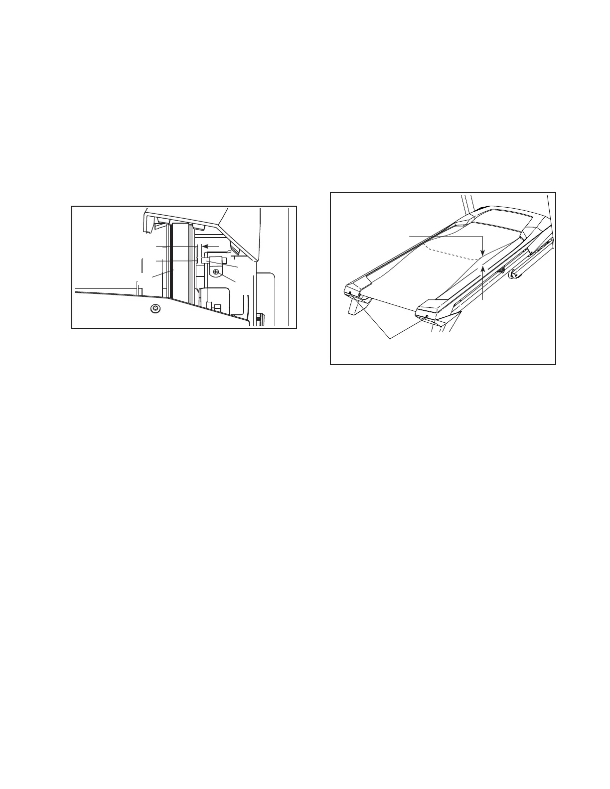
Locate the Reed Switch (85) and the Magnet (86)
on the right side of the Pulley (31). Turn the Pulley
until the Magnet is aligned with the Reed Switch.
If
necessary, loosen the #8 x 3/4" Truss Head Screw
(14), move the Reed Switch slightly, and then
retighten the Truss Head Screw. Carefully slide the
Motor Hood (not shown) back on by lining up the
guides. Reattach the Motor Hood with the five #8 x
3/4" Screws (not shown). Then, plug in the power
cord, insert the key, and run the treadmill for a few
minutes to check for a correct speed reading.
a. Hold down the Stop button and the Speed increase
button, insert the key into the console, and then
release the Stop button and the Speed increase
button. Next, press the Stop button and then
press the Incline increase or decrease button. The
treadmill will automatically rise to the maximum
incline level and then return to the minimum level.
This will recalibrate the incline system. If the incline
system does not begin calibrating, press the Stop
button again, and then press the Incline increase or
decrease button again. When the incline system is
calibrated, remove the key from the console.
a. If an extension cord is needed, use only a 3-con-
ductor, 14-gauge (1 mm
2
) cord that is no longer
than 5 ft. (1.5 m).
b. If the walking belt is overtightened, treadmill per-
formance may decrease and the walking belt may
become damaged. Remove the key and
Using the hex key, turn both
idler roller screws counterclockwise, 1/4 of a turn.
When the walking belt is properly tightened, you
should be able to lift each edge of the walking belt
2 to 3 in. (5 to 7 cm) off the walking platform. Be
careful to keep the walking belt centered. Then,
plug in the power cord, insert the key, and run the
treadmill for a few minutes. Repeat until the walk-
ing belt is properly tightened.
c. Your treadmill features a walking belt coated with
high-performance lubricant.
-
If you suspect that the walking belt needs more
lubricant, see the front cover of this manual.
d. If the walking belt still slows when walked on, see
the front cover of this manual.
86
31
85
14
1/8 in.
2–3 in.
b
Idler Roller Screws