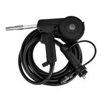
V1.0 200A SPOOL GUN KIT 8612517
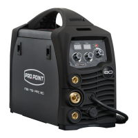
2. Connect the spool gun to the Euro torch connection socket
on the front panel, and tighten it. A loose connection can
result in the connector arcing and damaging the machine
and gun connector (Fig. 1-4).
3. Connect the spool gun’s control cable connector to the 9-pin
control socket on the front of the welding unit (Fig. 1-6).
4. Insert the earth cable plug into the negative socket on the
front of the machine and tighten (Fig. 1-3).
5. Connect weld power lead to the positive socket (Fig. 1-5).
6. Connect the gas line to the gas regulator. Then connect the
gas regulator to the gas cylinder (Fig. 1-1).
7. Turn the power source on and select the MIG function with
the MIG/TIG/MMA selector switch (Fig. 1-7).
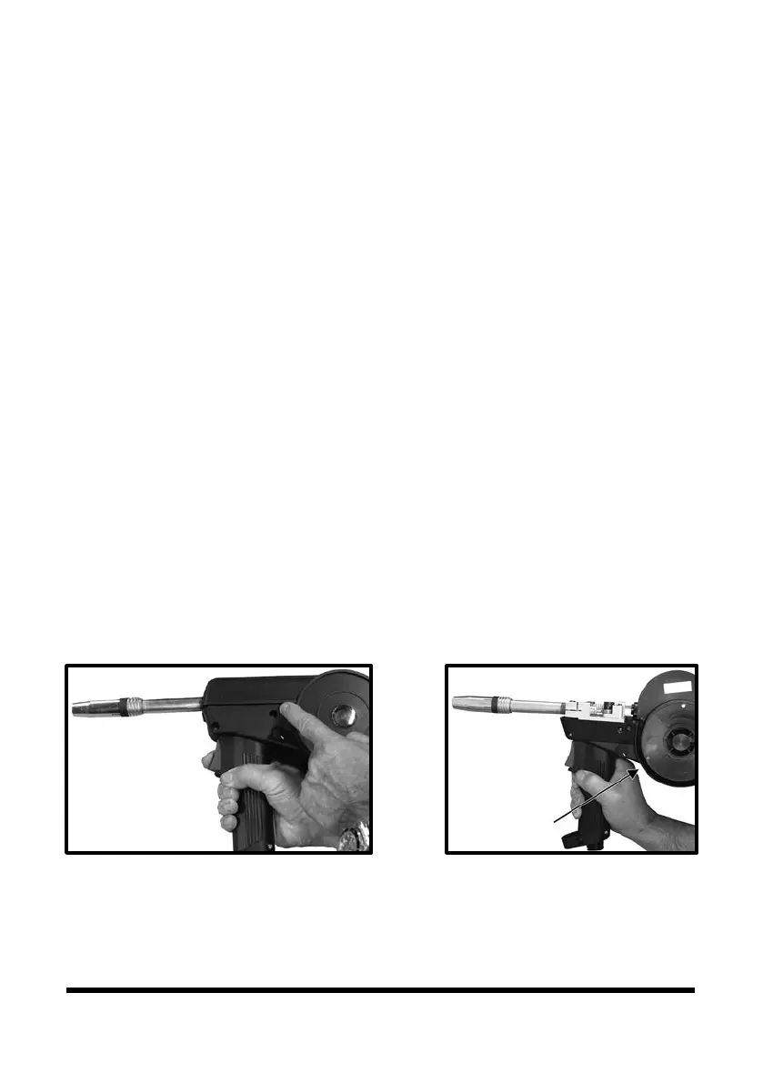
8. Press the cover release button to unlock the wire feed /
spool cover (Fig. 2)
9. Check that the drive roller being used complies with the
wire diameter, replace the roller if necessary.
10. Place the wire spool onto the spool holder (Fig. 3-1). The
spool retaining nut is a left-hand thread. Turn it clockwise
to undo it. Hold and snip the wire from the spool, being
sure to hold the wire to prevent rapid uncoiling.
11. Squeeze the tension arm adjustment knob to release the
pressure of the tension arm (Fig. 4-1). Carefully feed the
wire over the drive roller into the outlet guide tube, feed
through into the torch neck (Fig. 4-2).
Visit www.princessauto.com for more information 5