8612517 200A SPOOL GUN KIT V1.0
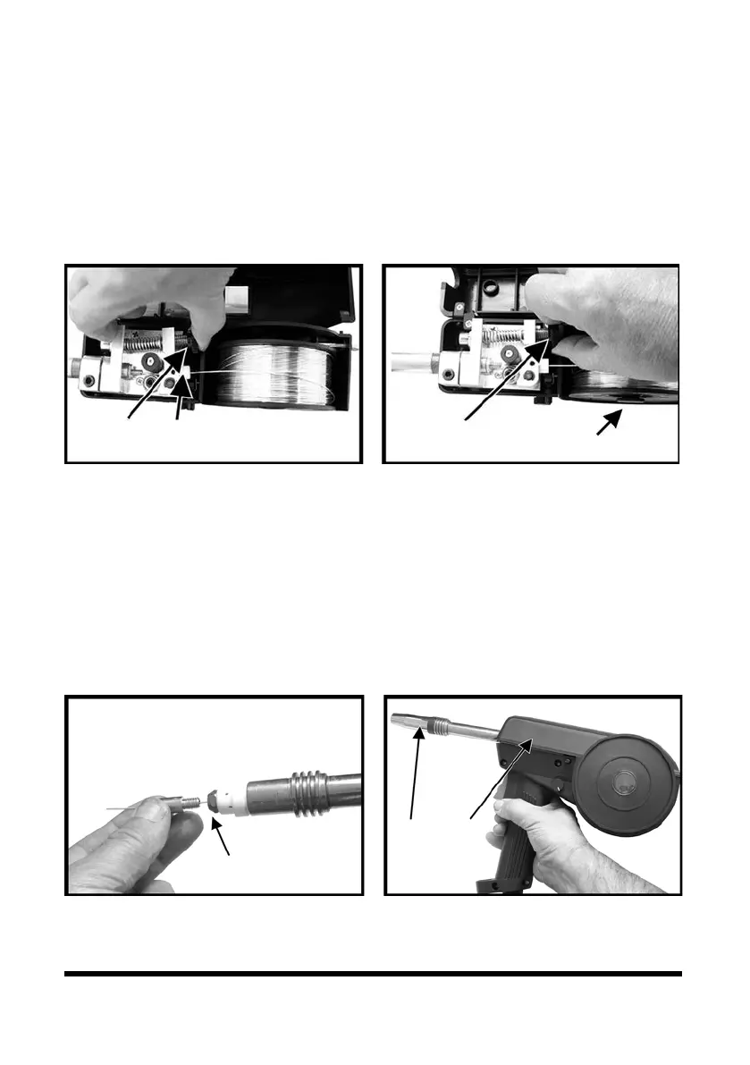
12. Align the wire into the groove of the drive roller and release
the tension arm. Check that the wire is in the drive roller’s
groove.
13. Apply an adequate amount of pressure to the drive roller
by winding in the tension adjusting knob (Fig. 5-1).
14. Adjust spool holder tension with the knob (Fig. 5-2).
15. Remove the gas nozzle and contact tip from the torch
neck, Pull the trigger to drive the wire through the neck
until it exits the contact tip holder (Fig. 6).
16. Fit the correct sized contact tip and feed the wire through
it, screw the contact tip into the tip holder of the torch
neck and nip it up tightly (Fig. 6-1).
17. Fit the gas nozzle to the torch head (Fig. 7-1) and close the
wire spool cover. (Fig. 7-2).
18. Follow the instructions in the welding machine manual to
set up the gas flow and welding parameters.
6 For technical questions call 1-800-665-8685