Warning
• It is not intended to be used on live wires with a DC power
source (e.g., live telephone lines), nor will it work on wire pairs
that are carrying AC signals.
• Use RJ45 SCAN compatible connector for RJ45 cable tracing.
Use RJ11(6 pin) connector for RJ11(6P/6C/4C/2C) cable tracing.
Use RJ11 (6 pin) connector and work with alligator clips for
coaxial cable, general cable and various wiring boards.
Caution
• To locate and isolate cables using the 1KHz analog toning mode,
please avoid interference sources like electronic devices with
adapter, induction coil, and motors nearby. White noise from
MT-7028 Receiver is normal when your Transmitter is near any
of the interference. If you cannot locate the signal on
2-conductor cables, the cable may be shorted. Please keep
away from the interference sources or turn off the electronic
devices.
• The position on the MT-7028 Transmitter and Receiver lets you
use the Receiver to trace using an analog 1KHz tone. When
using the Receiver to isolate the tone source in the cable bundle
or at the patch panel, the signal might be interfered with or
decreased and the signal will not pass through metal tubes.
• It is not necessary to touch the Receiver’s tip to the cabling or
patch panel when searching for the Transmitter’s signal.
• Make sure the black alligator clip of the Transmitter is connected
to the ground before use.
• When using the MT-7028 networking tone and probe kit with
earphone to locate and isolate cables, please keep probe tip
away from earphone to avoid the interference of resonance
effects
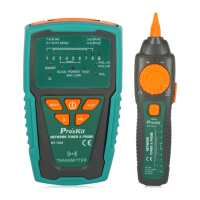
MT-7028 Transmitter provides two 1 KHz analog toning modes, Hi/Low
two-note tone, for location and isolating cables. Both toning signals are
available at all connectors on the Transmitter.
2.Locating Individual Wire Pairs with the MT-7028 Analog Function
To locate cables, do the following steps (Figure 1):
1) Connect the black alligator clip of the Transmitter to the ground,
and then connect the red clip to a jack or punch-down block as
shown in Figure 1.
 Loading...