Terminal Designations
This thermostat is shipped from the factory to operate a conventional heating
and cooling system. This thermostat may also be congured for a heat pump
system.
Wiring
Terminal
1 Heat 1 Cool
Conventional
System
RC
RH
C
B
O
G
W
Y
Transformer power
(cooling)
Transformer power
(heating)
Transformer
common
Fan relay
Heat Relay
Compressor
Relay
Wiring
Caution:
Electrical Hazard
All components of the control
system and the thermostat
installation must conform to
Class II circuits per the NEC Code.
Warning:
Do not overtighten terminal
block screws, as this can
damage the terminal block.
A damaged terminal block
can keep the thermostat
from tting on the subbase
correctly or cause system
operation issues.
Installation Tip
Max Torque = 6in-lbs.
Wiring
If you are replacing a thermostat,
make note of the terminal
connections on the thermostat that
is being replaced. In some cases
the wiring connections will not be
color coded. For example, the
green wire may not be connected
to the G terminal.
Loosen the terminal block screws.
Insert wires then retighten the
terminal block screws.
Place nonammable insulation into
the wall opening to prevent drafts.
1.
2.
3.
Wiring Tips
C Terminal
The C (common wire) terminal does
not have to be connected when the
thermostat is powered by batteries.
Wire Specications
Use shielded or non-shielded 18-22
gauge thermostat wire.
Failure to disconnect the power
before beginning to install this
product can cause electrical shock
or equipment damage.
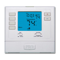
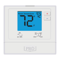
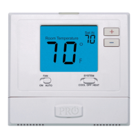
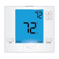
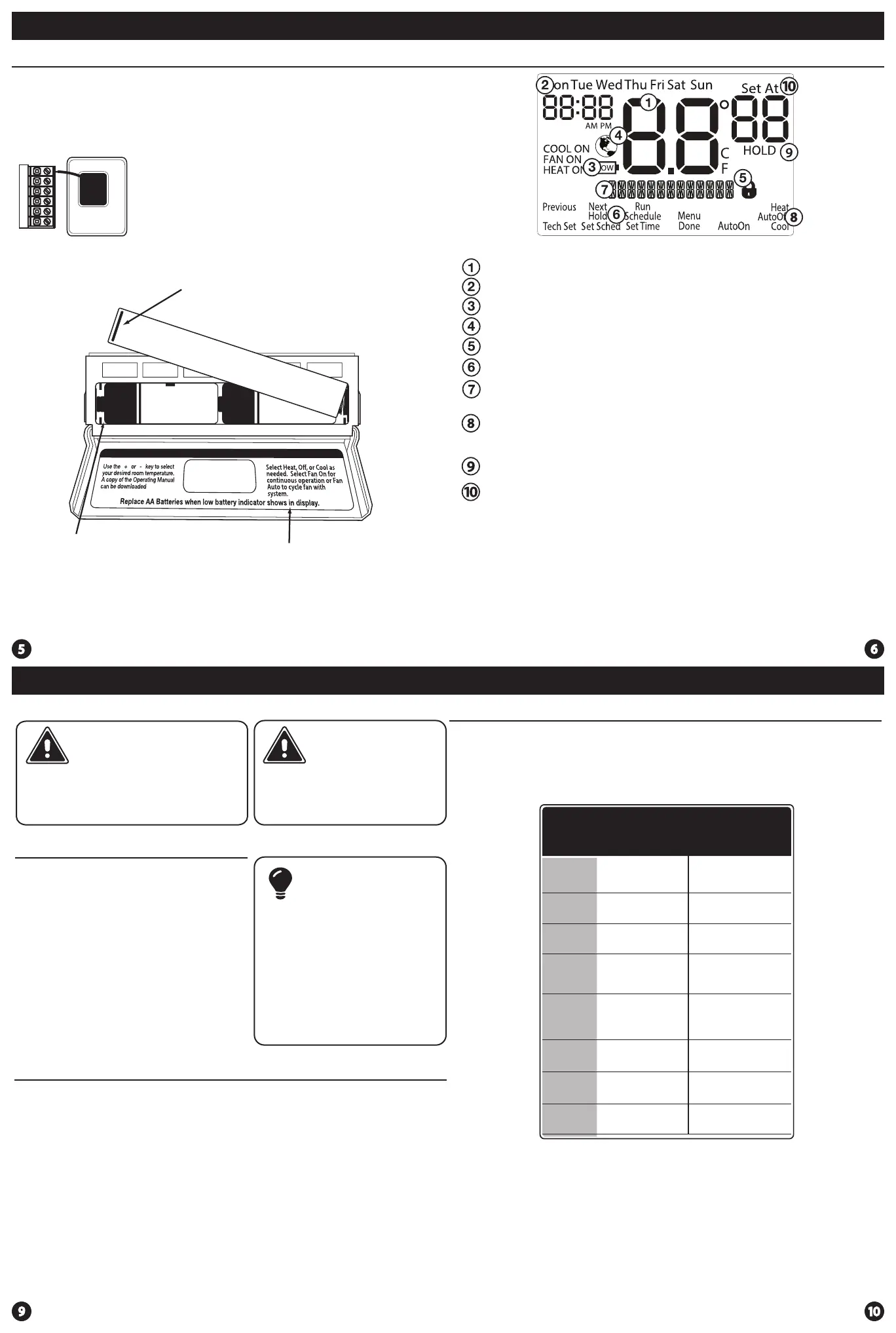
Thermostat Quick Reference
Displays the current room temperature
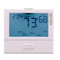
Time and day of the week
Setpoint: Displays the user selectable setpoint temperature.
Hold: is displayed when the thermostat program is permanently overridden.
System Operation Indicators:
If these or the Fan indicator are ashing, it means that the system is in a
delay of some type (compressor delay, cooling fan delay, staging delay).
Low Battery Indicator: Replace batteries when this indicator is shown.
Program Menu Options: Show dierent options during programming.
Program Time Periods - Residential: Uses 4 time periods - WAKE, RETURN,
LEAVE & SLEEP.
Getting to know your thermostat
Thermostat Quick Reference
Battery Installation
Battery installation is recommended even if the thermostat is
hardwired (C terminal connected). When the thermostat is hardwired
and batteries are installed, the thermostat will activate a compressor
delay of 5 minutes when it detects a power outage from the hardwired
power supply.
Important:
High quality alkaline batteries are recommended.
Rechargeable batteries or low quality batteries
do not guarantee a 1-year life span.
Insert 2 AA Alkaline batteries
(included). High quality alkaline
batteries are recommended.
Simple operating instructions
are found on the back of the
battery door.
To release battery cover press nger bevel
on the left side and lift the cover to access
batteries.
Keypad Lockout: Lock the thermostat
N/A
Energy Ecient Globe: Indicates ecient setpoint temperature.
N/A
1 Heat 1 Cool
Heat Pump
System
Transformer power
(cooling)
Transformer power
(heating)
Transformer
common
Changeover valve
energized in cooling
Changeover valve
energized in heating
Fan relay
N/A
1st Stage of heat
and cool
 Loading...