Proco Products, Inc. IOMSeries700R3 Page 8 of 13
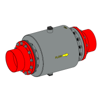
4.1.3.2 Step 2: External Clamps
Add the external clamps to the slip-on rubber check valve. For nominal diameters less than or equal
to 10” the check valve will be supplied with either T-Bolt or Worm Gear Clamps. For nominal
diameters greater than 10”, the check valve(s) will be supplied with fabricated stainless-steel
clamp(s). If the valve is supplied with more than one fabricated stainless-steel clamp, then rotate the
additional clamps which will place the clamping section at opposite angles from the first clamp. This
will ensure that even pressure is applied to the valve. Note: The supplied number of clamps will vary
depending on size and application.
Figure 16: Style 730/731 Installation Step 2
4.1.3.3 Step 3: Tighten Clamps
Tighten the external clamp until the rubber is
compressed by the external clamp and a tight fit
is achieved then proceed to section 4.1.8 for
anchor bolting/pinning to anchor the slip-on
check valve to the mating piping.
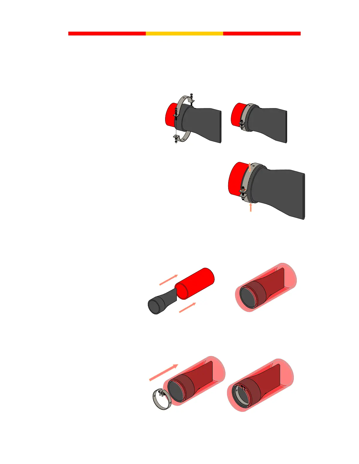
4.1.4 Style 740: ProFlex In-Line Slip-In Rubber Check Valve Installation
4.1.4.1 Step 1: Slip-In
Insert the slip-in check valve inside the existing pipe. For horizontal applications the bill of the
check valve must be installed in vertical orientation as shown below in Figure 15.
Figure 18: Style 740 Installation Step 1
4.1.4.2 Step 2: Insert Clamp
Insert and the expandable internal clamp into the rubber check valve. For dry or hot installations, it
is recommended to apply a layer of lubricant (such as Dow Corning 111 Compound) to the internal
expandable clamp to assist in proper placement and sealing of the clamp.
Figure 19: Style 740 Installation Step 2
Figure 17: Style 730/731