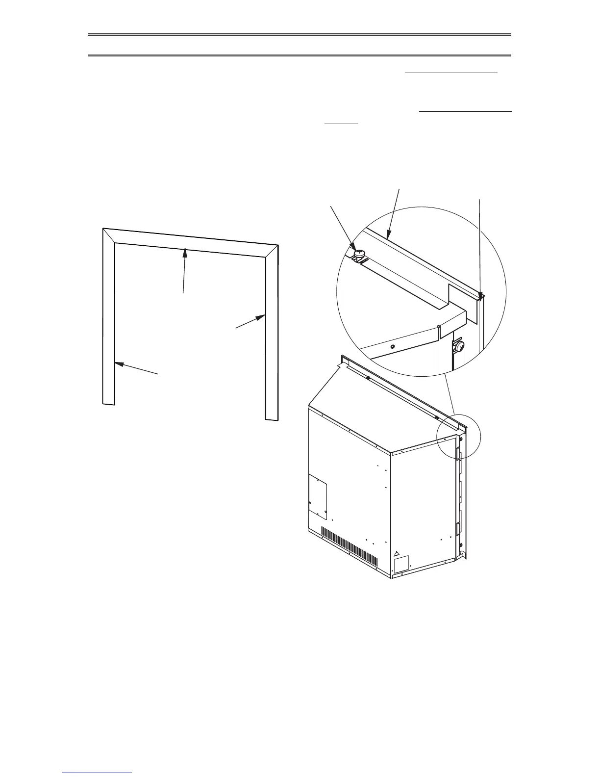
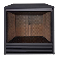
Top Trim Piece
Screw
Top Decorative Trim
Left/Right
Decorative
Trim
Left Trim Piece
Right Trim Piece
Figure 18 - Decorative Trim
Figure 19 - Installing Decorative Trim
INSTALLATION
4. Check all joints from equipment shutoff
valve to control valve (see Figure 16 or
17, page 16). Apply a noncorrosive leak
detection uid to all joints. Bubbles form-
ing show a leak.
5. Correct all leaks at once.
INSTALLATION FOR DECORATIVE TRIM
6. Light heater (see Lighting Instructions on
page 20). Check all other internal joints
for leaks.
7. Turn off heater (see To Turn Off Gas Ap-
pliance, page 21).
1. Identify left, right and top decorative trim
pieces (see Figure 18).
2. Slide slots in 3 trim pieces over screws on
the replace (see Figure 19).