- 13 -
3. Installation
3.1. Installation of the piping
CAUTION!
Inappropriate piping may result in damaging the compactor or carrier and shortening of its life.
Be sure to follow our regulations on pipe installation.
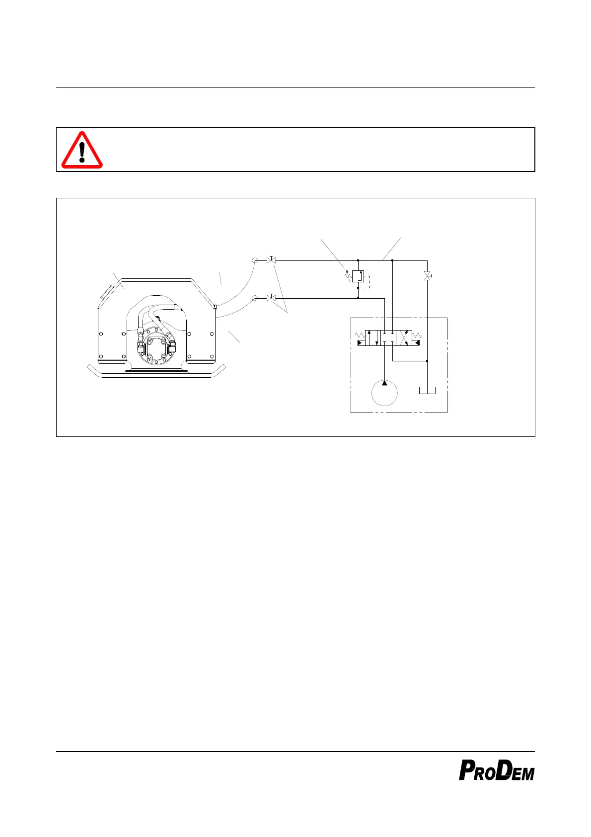
Hydraulic Circuit Diagram (recommended)
Compactor
'P' Port
(IN)
'T' Port
(OUT)
Stop Valve
Relief Valve
(See ※)
Drain line
(necessarily required)
Stop Valve for
by-directional
operation
(option)
★ Carrier's hydraulic systemmay vary depending
on the model and maker.
P
T
P
T
A
B
Figure 12 The above circuit diagram is for reference only.
The specifications of carrier’s hydraulic system required to operate the compactor is as follows.
Pump Flow: Higher than the minimum working flow of the compactor
System Pressure: 180 bar or higher
Allowable Back-Pressure: 15 bar or less
Compactor piping is basically the same as breaker piping, and thus it is possible to use the breaker piping
as it is without any modification.
★ But, the drain(low-pressure) line must be connected directly to oil cooler or oil tank.
If the drain line is connected to the control valve of the carrier, the compactor’s motor can be
damaged.
If the drain line of carrier has a stop valve for by-directional operation, be sure to operate the compactor
with opening the stop valve.
The drain line should has sufficiently large inner diameter to meet the specified maximum acceptable
back-pressure of the compactor. If the back pressure – measured at the ‘T’ port during operation – is
higher than the specified value, check the inner diameters of pipes, hoses or fittings of the drain line.