11
ENG ITA
Come sopra, ma per l'ingresso del canale 2, questo è un connettore
combinato che accetta sia XLR che JACK. È attivo solo in modalità
STEREO.
18. Uscita XLR Canale 1
Questo è un connettore XLR maschio connesso in parallelo con il rispettivo
connettore XLR femmina di ingresso del canale 1, rendendo possibile il
collegamento in cascata di una seconda unità. In questo modo è possibile
inviare lo stesso segnale a più ampli catori, per formare un più complesso
e potente sistema di rinforzo del suono.
19. Uscita XLR Canale 2
Questo è un connettore XLR maschio connesso in parallelo con il rispettivo
connettore XLR femmina di ingresso del canale 2.
20. Selettore HPF / BI-AMP / FLAT
Questo selettore permette la selezione di una delle seguenti funzioni:
• In HPF abilita un ltro passa alto a 100Hz LR-24dB/Oct. per entrambi i
canali: utile per ltrare altoparlanti SAT-TOP o MONITOR DI PALCO.
• In BI-AMP abilita un crossover Linkwitz-Riley 24dB/Oct. a 100Hz fra il
canale 1 e il canale 2: ciò permette ad un singolo ampli catore (senza
un processore dedicato) di pilotare un SUB-WOOFER con il canale 1 e un
SAT-TOP SPEAKER con il canale 2 (vedi anche gli esempi di connessione
più avanti in questo manuale).
• In FLAT nessun ltro è inserito nel percorso del segnale.
21. Interuttore GND LIFT
Questo interuttore solleva la massa degli ingressi audio bilanciati dalla
massa-terra dell'ampli catore. Se si hanno problemi di ronzio su uno o
più altoparlanti provare a cambiare la posizione di questi interruttori:
perchè abbiano e etto spesso occorre siano tutti su o tutti giù per tutti
gli ampli catori e che tutti i cavi siano bilanciati.
22. Selettore STEREO - PARALLEL - BRIDGE
Permette la selezione delle modalità di funzionamento in STEREO,
PARALLEL o BRIDGE.
• In modalità STEREO ogni canale dell'ampli catore è indipendente
dall'altro e pilotato dal rispettivo ingresso.
• In modalità BRIDGE entrambi i canali dell'ampli catore funzionano
assieme ma con il canale 1 in fase e il canale 2 fuori fase, entrambi i canali
dell'ampli catore sono pilotati dall'ingresso del canale 1 e l'uscita deve
essere prelevata dall'uscita speakon "BRIDGE".
• In modalità PARALLEL entrambi i canali dell'ampli catore sono pilotati
insieme dall'ingresso del canale 1. (Nota: usare questa impostazione se si
vuole usare anche l'impostazione BI-AMP).
23. Uscita SPEAKON Channel 1
Connettore Neutrik Speakon NL4C maschio, collegato come segue:
• PIN 1+ collegato all'uscita POSITIVA del canale 1;
• PIN 1- collegato all'uscita NEGATIVA del canale 1;
• PIN 2+ collegato all'uscita POSITIVA del canale 2;
• PIN 2- collegato all'uscita NEGATIVA del canale 2;
Se si collega un cavo standard a due li (1+/1-), si invia all'altoparlante
il segnale ampli cato del canale 1.
Se si collega un cavo standard a 4 fili (1+/1-/2+/2-), si invia
all'altoparlante:
• con l'ampli catore in modalità STEREO, le uscite ampli cate del segnale
applicato all'ingresso del canale 1 (1+/1-) e del canale 2 (2+/2-), o
• con l'amplificatore in modalità PARALLEL,le uscite amplificate del
segnale applicato al solo ingresso del canale 1 (1+/1-) = (2+/2-),
which accepts a XLR or a JACK plug. It operates only in STEREO mode.
18. Channel 1 XLR output
This XLR male connector is connected in parallel with the respective XLR
input female connector of Channel 1. This enables a second unit (e.g.
another ampli er) to be daisy-chained to the rst. It’s thus possible to
power several ampli ers using the same signal, forming more powerful
sound reinforcement systems.
19. Channel 2 XLR output
This XLR male connector is connected in parallel with the respective XLR
female connector of Channel 2.
20. HPF / BI-AMP / FLAT selector
This useful switch allow the selection of one of the followig features:
• In HPF enables a 100Hz LR-24dB/Oct. High Pass Filter for both channels:
this a useful feature for SAT-TOP SPEAKERS or STAGE-MONITORS.
• In BI-AMP enables a Linkwitz-Riley crossover 24dB/Oct. at 100Hz
between channel 1 and channel 2, then allows a single ampli er (without
a dedicated processor) to drive a SUB-WOOFER with channel 1 and a
SAT-TOP SPEAKER with channel 2 (see also connection examples further
on this manual).
• In FLAT no lters are inserted in the signal path.
21. GND LIFT switch
This switch lift the ground of the balanced audio inputs from the earth-
ground of the ampli er. If you have HUM noise problem on one or more
loudspeaker try to change the position of these switches (often all up or
all down for whole ampli ers in the system). Please note that to have an
e ect all cables must be balanced.
22. STEREO / BRIDGE / PARALLEL mode selector
Allows the selection of STEREO, PARALLEL or BRIDGE mode operations.
• In STEREO mode each ampli er channel runs indipendently driven by
respective input.
• In BRIDGE mode both amplifier channels run toghether but with
channel 1 in phase and channel 2 out of phase, both channels are driven
by Channel 1 input and the output must be taken from "BRIDGE" speakon
output.
• In PARALLEL mode both ampli er channels run together driven by
Channel 1 input. (Note: use this setting if your intention are to use the
BI-AMP feature also).
23. Channel 1 SPEAKON output
Accepts a male Neutrik Speakon NL4C connector wired in this way:
• PIN 1+ connected to POSITIVE output of Channel 1;
• PIN 1- connected to NEGATIVE output of Channel 1;
• PIN 2+ connected to POSITIVE output of Channel 2,
• PIN 2- connected to NEGATIVE output of Channel 2,
If you connect a standard 2 wire cable (1+/1-), you run to the speaker the
ampli ed output of the signal applied to channel 1 input.
If you connect a standard 4 wire cable (1+/1-/2+/2-), you run to the
speaker:
• with ampli er set in STEREO mode, the ampli ed outputs of the signal
applied to channel 1 input (1+/1-) and to channel 2 input (2+/2-), or
• with ampli er set in PARALLEL mode, the ampli ed outputs of the
signal applied to channel 1 input only, (1+/1-) = (2+/2-),
In both modes using a single cable you can connect a BI-AMP loudspeaker
or a SUB-SAT speaker system.
Always connect a louspeaker with a minumum impedance of 4 ohm or
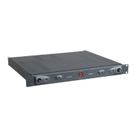
REAR PANEL
PANNELLO POSTERIORE