25
ENG ITA
certain to always use only power cables for
speakers and not signal cables.
Normally these connectors provide the
ampli ed signal of the MAIN MIX bus (106) or,
as speci ed above, the ampli ed signal of any
output or source connected to the AMPLIFIER
INPUTS L&R (117).
Each ampli er's channel has a built-in LIMITER
to avoid excessive distortion: use the LED
METER (112) to display the MAIN MIX (76)
signal and to check when the LIMITER is
working.
IMPORTANT: in order to get from the built-in ampli er the maximum
power without excessive signal compression and/or distortion, when
the meter displays the MAIN MIX level, you should avoid the signal to
exceed continously the AMP LIMIT mark (86).
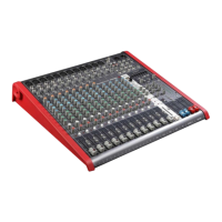
120. AIR VENTS
Air vents for the ampli er’s cooling.
IMPORTANT: IN ORDER FOR THE MIXER TO WORK CORRECTLY, IT’S
VERY IMPORTANT TO KEEP THE AIR VENTS ALWAYS FREE AND ABLE TO
PROVIDE A PROPER AIR CIRCULATION.
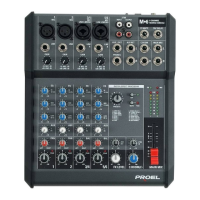
121. AC~ socket
Here’s where you plug in your mixer’s mains supply cord. You should
always use the mains cord supplied with the mixer. Be sure your mixer
is turned o before you plug the mains supply cord into an electrical
outlet.
122. POWER switch
Use this switch to set the mixer power to ON or OFF. Make sure that all
master output knobs are turned all the way down when powering your
mixer up or down.
123. +48V phantom switch CH1-8
This switch activates and deactivates the phantom power on CH1-8 MIC
Inputs. Most professional condenser microphones require phantom power,
which is a lower DC voltage delivered to the XLR microphone connector.
Dynamic microphones
do not require phantom
power, however
phantom power
will not harm most
dynamic microphones
should you accidentally
plug one in while the
phantom power is on.
Check the manual of
your microphone to
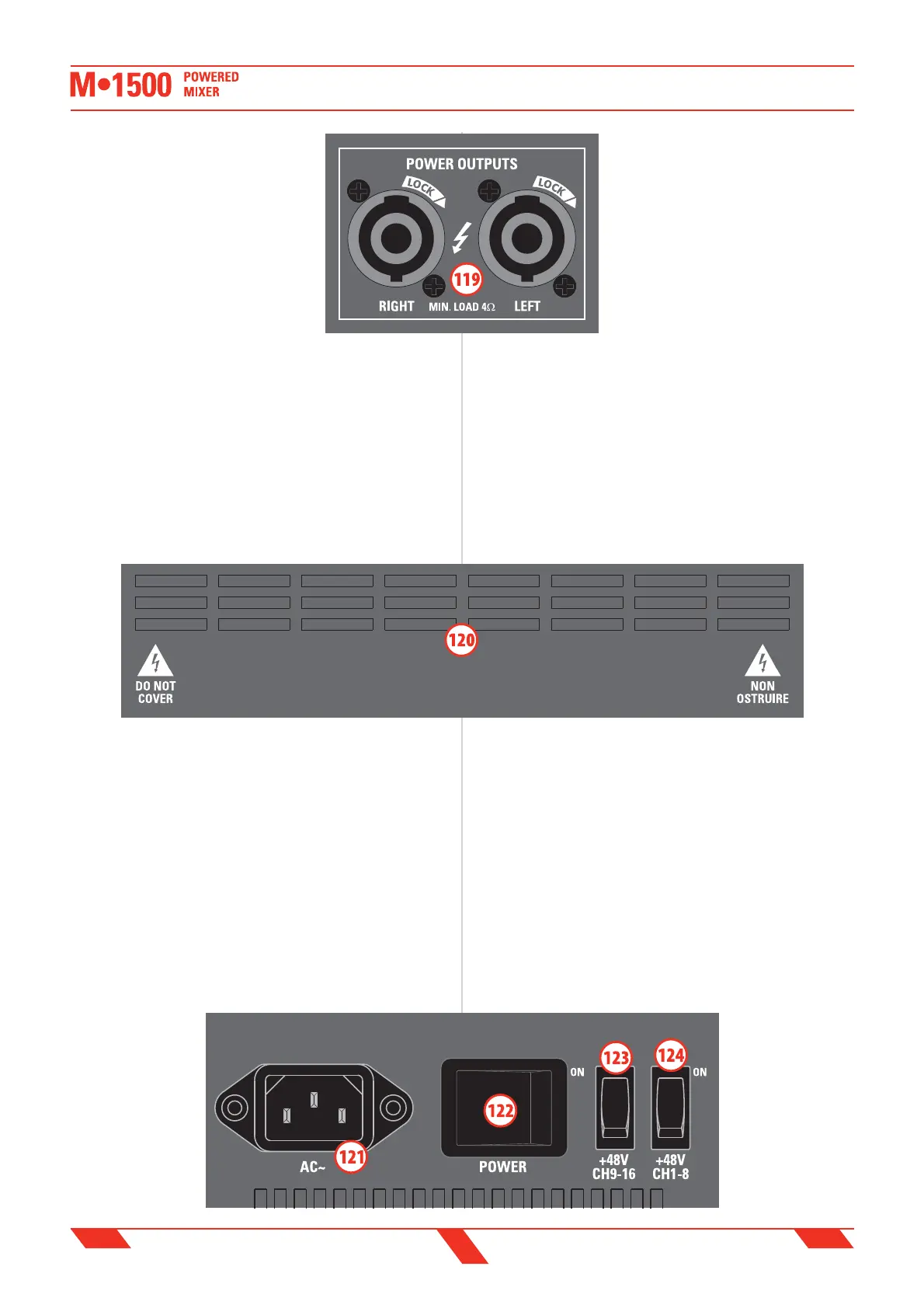
119. POWER OUTPUTS L & R speakon
output
Questi connettori speakon sono le uscite
dell'amplificatore interno da 750+750W:
collegare queste uscite agli altoparlanti.
IMPORTANTE: assicurarsi che l'impedenza
degli altoparlanti non sia inferiore a 4
ohm, altrimenti l'amplificatore andrà in
protezione. Assicurarsi sempre di usare
esclusivamente cavi di potenza adatti per
collegare gli altoparlanti e non cavi di
segnale.
Normalmente questi connettori restituiscono il segnale ampli cato del
bus MAIN MIX bus (106) o, come speci cato sopra, il segnale ampli cato
di qualsiasi sorgente connessa agli ingressi jack AMPLIFIER INPUTS L&R
(117).
Ciascun canale dell'ampli catore ha un limitatore interno di segnale
(LIMITER) che previene una distorsione eccessiva: usare gli indicatori
di livello LED METER (112) per visualizzare il segnale MAIN MIX (76) e
controllare quando il LIMITER stà lavorando.
IMPORTANTE: per ottenere dall'ampli catore interno il massimo
della potenza evitando una eccessiva compressione o distorsione
del segnale, quando i meter visualizzano il livello del MAIN MIX,
si consiglia di non oltrepassare in modo persistente il livello
contrassegnato dall'indicazione AMP LIMIT.
120. PRESE D'ARIA
Prese d’aria per il ra reddamento dell’ampli catore interno.
IMPORTANTE: PER NON COMPROMETTERE IL CORRETTO
FUNZIONAMENTO DELL’AMPLIFICATORE, E’ MOLTO IMPORTANTE CHE
LA PRESA D’ARIA SIA MANTENUTA SEMPRE LIBERA, PER CONSENTIRE
UNA CORRETTA CIRCOLAZIONE DELL’ARIA DI RAFFREDDAMENTO.
121. AC~ (presa di alimentazione di rete)
In questa presa va inserito il cavo di alimentazione di rete del mixer.
Si raccomanda di utilizzare esclusivamente il cavo di alimentazione in
dotazione al mixer. Accertatevi che il mixer sia spento prima di inserire il
cavo di alimentazione
nella presa di corrente.
122. POWER
(interruttore di
accensione)
Agite su questo
tasto per accendere
o spegnere il mixer.
Assicuratevi che tutte i
livelli di uscita siano al