22
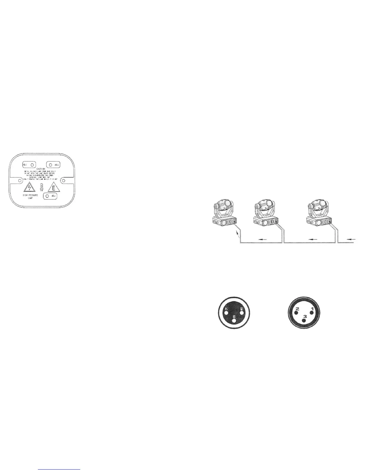
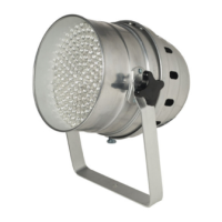
LAMP ADJUSTMENT
The lamp holder is aligned at the factory. Due to differences between lamps, fine
adjustment may improve light performance
Strike the lamp, open the shutter and the iris, set the dimmer intensity onto 100% and
If the light is brighter around the edge than it is in the center, or if light output is low, the
lamp is too far back in the reflector. “Push” the lamp out by turning the screws “A, B, C”
counterclockwise 1/4-turn at a time the light is bright and evenly distributed
RIGGING
DANGER TO LIFE: Please consider the respective national norms during the installation.
The installation must only be carried out by an authorized dealer.
The installation must always be secured with a secondary safety attachment. This
secondary safety attachment must be constructed in a way that no part of the installation
can fall down if the main attachment fails.
When rigging, derigging or servicing the fixture staying in the area below the installation
place, on bridges, under high working places and other endangered areas is forbidden.
The operator has to make sure that safety-relating and machine-technical installations
are approved by an expert before taking into operation for the first time and after
changes before taking into operation another time.
IMPORTANT: OVERHEAD RIGGING REQUIRES EXTENSIVE EXPERIENCE, including
(but not limited to) calculating working load limits, installation material being used, and
periodic safety inspection of all installation material and the projector. If you lack these
qualifications, do not attempt the installation yourself, but instead use a professional
structural rigger. Improper installation can result in bodily injury and. or damage to
property.
The projector has to be installed out of the reach of people.
If the projector shall be lowered from the ceiling or high joists, professional trussing
11
1. sostegni a omega (per collegamento alla truss)
2. gancio di fissaggio alla truss (es. aliscaf - opzionale)
3. vite
4. fune di sicurezza
5. foro di passaggio per ancoraggio fune di sicurezza
Avvitare ciascun aliscaf con una vite M12 ai sostegni ad omega.
Fissare il primo sostegno ad omega avvitando le due viti nei rispettivi fori posti al di sotto
della base; allo stesso modo fissare il secondo sostegno.
ATTENZIONE: prima di intraprendere qualsiasi operazione per la prima volta, il tipo di
installazione deve essere approvata da personale esperto
CONNESSIONE CON UNA CENTRALINA DMX / CONNESSIONE FRA APPARECCHI
I cavi non devono venire a contatto con altri cavi, in tal caso infatti gli apparecchi
potrebbero non funzionare correttamente o non funzionare affatto.
Usare solo cavi stereo schermati con spina e presa tipo XLR 3 poli, per la connessione
alla centralina DMX o per il collegamento tra apparecchi.
SCHEMA DI CONNESSIONE DEI CAVI DMX: