32
WP-250 General
Operating Instructions
The PROFAX Welding Positioner is designed for light loads, with a maximum load of 250 lbs. when the table is in a vertical position and 440
lbs. when it is in the horizontal position.
Loading the Positioner
The positioner may be floor or bench mounted. When mounting the positioner on a bench it is advisable to secure it solidly to the bench to
avoid any possibility of tipping over with a load. See figure 1 for mounting dimensions.
When loading the work piece onto the table it is important that the following guide lines are followed to avoid over turning the positioner and/or
overloading the motor and gear train.
1. Determine the total weight of your work piece including all fixtures, chucks, brackets, etc.
Note: This must not exceed 250 lbs. with the table in the vertical position or 440 lbs. with the table in the horizontal position.
2. Locate the center of gravity of the work piece with any fixtures attached.
3. Mount the work piece to the turn table making sure that the center of gravity is within 4” of the center of the turn table as shown in figure
No. 2.
Warning! Use equipment of a proper size to lift and/or move the weldment onto the positioning table. Falling equipment can cause personal
injury and/or equipment damage.
Welding Cable Ground (Work) Connection
The positioning table is grounded by means of a brush which contacts the underside of the table. See Figure 3. Connection to this is by
means of a welding cable lug. Attach the welding cable lug to a properly sized welding cable and then attach the lug to the brush holder by
means of the bolt provided. Tighten the bolt securely. The brush has a maximum allowable welding current of 200 amps. Do not attempt to
run higher than 200 amps through the grounding brush. Welding currents greater than 200 amps should be grounded directly to the work
piece by means of a proper ground clamp.
Service or repair of this unit must be done by qualified personnel only.
Warning! Before performing any maintenance on this control circuit disconnect the unit from any power supply.
®
®
®
®
Figure No. 2
Figure No. 3
Turn Table in Vertical PositionTurn Table Face
4” Radius
4”
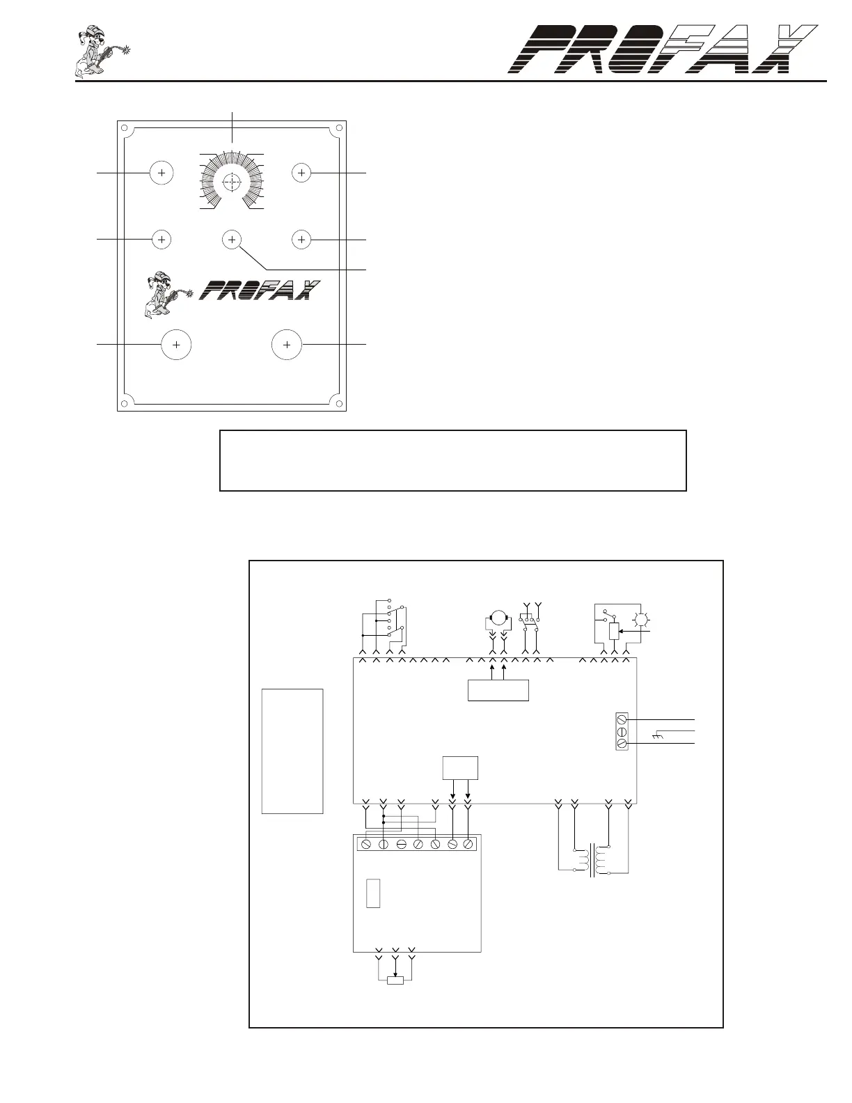
Control Panel & Wiring Diagram
Wiring Schematic
1. Pilot Light: Lights up red to indicate power on.
2. Power On-Off Switch
3. Speed Control: Provides control of table rotation speed from 0%(0 RPM) to
100%(5 RPM).
4. Fuse Holder: Fuse 5 amp
5. Forward/Off/Reverse Switch: Controls table rotation. Forward (clockwise
rotation) and Reverse (counterclockwise rotation).
6. Remote/Panel Switch: Remote = Start and stop are remotely controlled.
Panel = Start and stop are operated from the control box.
7. Remote Plug: Plug-in for the foot switch to start and stop of the turn table
rotation.
8. Power in
0
10
20
30
40
POWER
FUSE
50
100
90
80
70
60
ON
OFF
FOOT SWITCH
FORWARD
OFF
REVERSE
POWER IN
®
®
REMOTE
SPEED
PANEL
Do Not Switch Under Load
1
2
3
4
5
6
8
7
CAUTION! - Switching rotation direction before coming to a complete
stop may damage motor and/or gear box voiding warranty.
5K
1
2
U
U
GG Y
R
W W
S
KB
O
OB
F
1
G
W
R1
U
P
N
W
O
C
L1
F-
F+
A-
A+ L2
F
2
CT
Y
Min Max
125V
4A
PC2
L1
B
Line
Gnd.
Line
L2
CN1
CN2
CN6
PC1
M
P
Off
On
125V / 5A
B
0 to90VDC
w / Ref. to R1
115VAC
to PC2
15VAC
B = Black
G = Green
K = Pink
N = Brown
O = Orange
P = Purple
R = Red
S = Gray
T = Tan
U = Blue
W = White
Y = Yellow
Forward
Off
Reverse
CN3
CN5
CN4
RC1
Panel
Remote
115VAC for WP250
or
220VAC for WP250-2
 Loading...