®
®
4
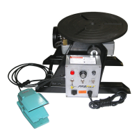
NO. PROFAX DESCRIPTION
1. PX9912 Control Box Complete
2. PX9913 Motor
3. PX9914 Worm Gear
4. PX9915 Shaft, Gear, and Bushing Assembly
5. PX9916 Hand Wheel
6. PX9917 Turn Table
7. PX9918 Grounding Brush & Holder
WP-250 Parts List
NO. PROFAX DESCRIPTION
8. PXCFS-302 Foot Control Switch
9. PX9924 Fuse, Power 5A (Not Shown)
10. PX9925 Fuse, PC2 4A (Not Shown)
11. PX9926 Tilt Lock
12. PX9927 Tilt Lock Securing Bolt
13. PX9928 Tilt Lock Handle
6
5
4
12
13
11
8
1
2
7
3
TROUBLE SHOOTING
1. No power 1. Check power supply for 115VAC 50/60Hz.
Indicator Light Fails to light 2. Fuse blown 2. Check and replace fuse.
3. Faulty indicator light 3. Check and replace indicator light.
4. Faulty power switch 4. Check and replace power switch.
1. Faulty PC board 1. Check and replace control box (see item 1 below).
Fuse blown 2. Faulty motor 2. Check and replace motor.
3. Faulty or bad transformer 3. Check and replace control box (see item 1 below).
1. Faulty PC board or control box 1. Voltage to motor should vary from 0 to 90VDC in relation to the
speed control. If output is erratic or non-existing replace control box.
Table fails to turn 2. Faulty motor 2. Check and replace motor.
3. Faulty forward/off/reverse switch 3. Check to see if switch is in correct position. Must be in either
forward or reverse position to run. Test switch continuity.
Table will not tilt 1. Tilt lock engaged 1. Release tilt lock.
PROBLEM POSSIBLE CAUSE SOLUTION
®
®
Daily Maintenance
*NOTE: INSPECT & REPAIR BEFORE OPERATION.
• Inspect table ground for proper ground tension against table. (Positioners)
• Check oil level in gear cases & fill if necessary. (WP-500/WP-1000/WP-2000)
• Inspect foot pedal and/or pendant for proper operation.
• Test limit switches if applicable.
• Test operation of power switch and/or emergency stop button.
• Check for any broken wires, loose connections, worn parts or damages before operation.
• Apply grease to all gears and grease fittings. (Weekly)
 Loading...