10 11
INSTALLATION CONNECTIONS
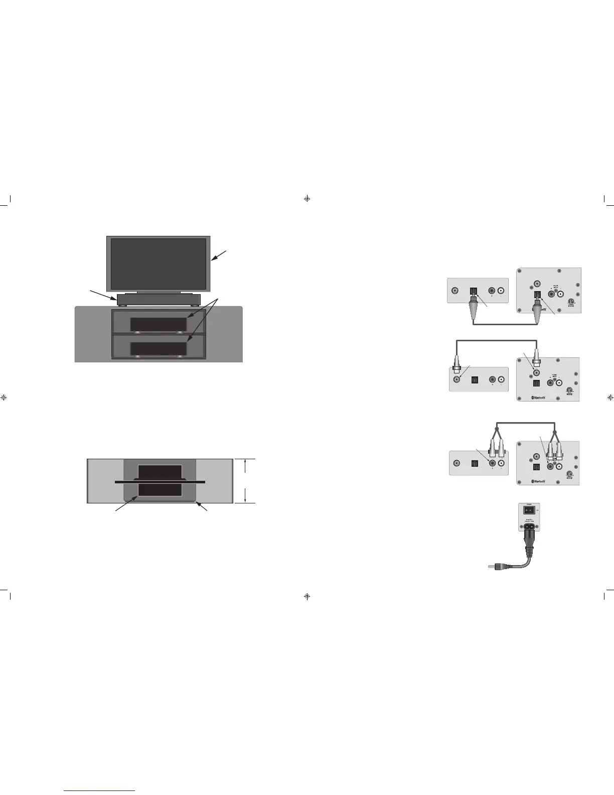
Flat Screen
TV
MaxTV
A/V Sources
TABLE TOP INSTALLATION
The MaxTV MT2 is ideally designed for table top installation. In this application the MT2 is placed on a cabinet top and becomes a
pedestal for the TV. Very little space beyond that already used by the TV is required.
DOWN-FIRING SUBWOOFERS/REAR PORTS
The MT2 has two down-firing subwoofers. The MT2 should always be placed on a solid surface, maintaining the clearance on the
bottom of the unit required for low-frequency sound to freely radiate into the room. Do not place objects next to the MT2 that
will block this space...on any side...as this can also adversely affect low-frequency performance. The MT2 has two rear bass ports
that enhance low frequency sounds. These ports should remain unobstructed with a clearance of at least three inches to a back
wall to assure proper performance.
Cabinet Depth
17" minimum
TV pedestal should not
be larger than the top of the MT2
(W 28" x D 16")
TV Pedestal
MaxTV
CABINET DEPTH
The cabinet top should be at least seventeen inches deep to properly support the MT2. The MT2 is sixteen and a half inches deep
(with grille attached) and extra space will be required between the MT2 and a wall behind the cabinet for cables connecting the
MT2 to the TV or other A/V sources (3 inches minimum).
PEDESTAL DIMENSIONS
The TV pedestal should not be larger than the top of the MT2 (W 28" x D 16"). A TV with a pedestal larger than the MT2 top will not
be properly supported. Place a TV with a pedestal larger than 28" x 16" directly on the cabinet and locate the MT2 on a shelf below
the T V.
OPTICAL
INPUT
COAXIAL
INPUT
COAXIAL
OUTPUT
OPTICAL
OUTPUT
AUDIO
OUTPUT
TV/Source Audio Outputs
MaxTV Audio Inputs
Digital Coaxial Audio Cable
TV/Source
Coaxial OUTPUT
MaxTV
Coaxial INPUT
4005723
OPTICAL
INPUT
COAXIAL
INPUT
COAXIAL
OUTPUT
OPTICAL
OUTPUT
AUDIO
OUTPUT
TV/Source Audio Outputs
MaxTV Audio Inputs
Digital Optical Audio Cable
TV/Source
Optical OUTPUT
MaxTV
Optical INPUT
4005723
OPTICAL
INPUT
COAXIAL
INPUT
COAXIAL
OUTPUT
OPTICAL
OUTPUT
AUDIO
OUTPUT
TV/Source Audio Outputs
MaxTV Audio Inputs
Stereo RCA Patch Cable
TV/Source
L&R Audio OUTPUTS
MaxTV
L&R Audio INPUTS
4005723
HARDWIRED AUDIO CONNECTIONS
MaxTV MT2 has three hardwired Audio Input connections on the rear panel that can be used for TV audio or connection to other
sources such as CD player, a portable music player (that does not have bluetooth), a computer or any audio source with one of the
following output connections. For Bluetooth connection, see section: Pairing and Selecting a Bluetooth Source.
COAXIAL DIGITAL AUDIO
Connect the Coaxial Digital Audio OUT on a TV or other
source to the MT2 Coaxial Input using a Coaxial Optical
Audio Cable as shown. This Input is selected by pressing
the ‘COAX’ button on the included IR Remote.
NOTE: The audio output of a TV, Blu-ray Disc player or
DVD player connected to the MT2 via Coaxial Digital,
must be set to PCM in the source’s setup. Please see the
device Owner’s Manual for details. Digital connection to
a CD player does not require a special setting.
L&R AUDIO
Connect the L&R Audio OUT on a TV or other source to
the MT2 L&R Audio Input using a Stereo RCA-RCA Patch
Cable as shown. This Input is selected by pressing the
‘AUX’ button on the included IR Remote.
OPTICAL DIGITAL AUDIO
Connect the Optical Digital Audio OUT on a TV or other
source to the MT2 Optical Input using a Digital Optical
Audio Cable as shown. This Input is selected by pressing
the ‘OPT’ button on the included IR Remote.
NOTE: The audio output of a TV, Blu-ray Disc player or
DVD player connected to the MT2 via Optical Digital,
must be set to PCM in the source’s setup. Please see the
device Owner’s Manual for details. Digital connection to
a CD player does not require a special setting.
AC POWER CORD
After all audio connections have been made and con-
firmed, connect the female end of the included power
cord to the AC Input on the MT2 rear panel, and then
plug the AC power cord into an unswitched AC outlet.
The AC connection is a universal power connection that
will automatically switch AC voltage from 100-240VAC.
Turn the Power switch ON.
FRONT VIEW
TOP VIEW
 Loading...