9
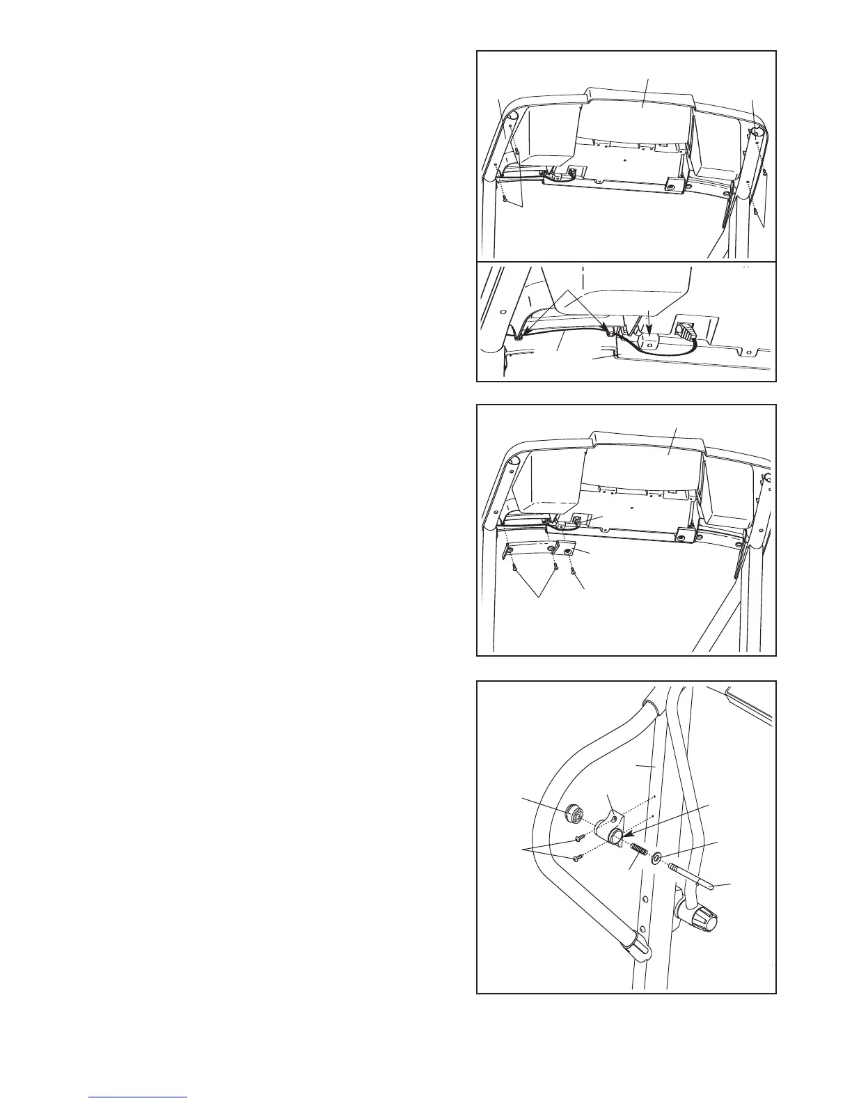
10.Attach the Latch Housing (29) to the left Upright (69) with
two 3/4" Screws (2). Make sure that the large hole in
the Latch Housing is on the side shown.
Remove the knob from the pin. Make sure that the col-
lar and the spring are on the pin as shown. Then, in-
sert the pin into the Latch Housing (29), and tighten the
knob back onto the pin.
11.
Make sure that all parts are properly tightened be
-
fore you use the treadmill. Note: Extra hardware may
be included. Keep the included hex keys in a secure
place; the large hex key is used to adjust the walking
belt (see page 26). To protect the floor or carpet, place a
mat under the treadmill.
Pin
Collar
Spring
Knob
69
29
2
10
Large
Hole
42
36
47
9. Cover the Upright Wire (42) with the Right Grip Plate
(36). Be careful not to pinch the Upright Wire. Tighten
two 1/2" Screws (48) and the 3/4" Screw (2) into the
Right Grip Plate and the Console Base (47).
48
2
9
4
7
8. Set the Console Base (47) on the Handrails (71, 72).
Attach the Console Base with four 3/4" Screws (2). Start
a
ll four Screws before tightening any of them; do not
overtighten the Screws.
See the lower drawing. Make sure that the Upright
Wire (42) is routed below the two indicated round
posts (A). Next, press the Upright Wire into the slot be-
tween the square post (B) and the Console Base (47).
2
2
72
71
8
A
47
42
B