USER
I
NTERFA
CE
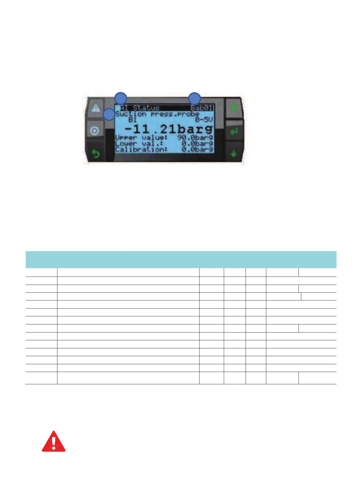
Screen for displaying/setting the parameters
An example of visual for displaying/setting the parameters is shown in the figure, also
highlighting the fields and icons used:
3
2
1
1. Parameters
2. Screen identifier
3. Menu
The display identifier details the menu branch and the mask:
the first character indicates the
menu branch, while the two alphanumeric digits identify the order of the mask inside the
menu. For example mask Bab01 is the first mask in menu B.a.b
Paramètres de
consigne
(valeurs données à titre
indicati
f
)
Description Unit Min
Suction high pressure alarm threshold
Suction low pressure alarm threshold
Minimum on time compressor
Minimum off time compressor
Minimum time to start same compressor
High gas cooler pressure alarm threshold
Low gas cooler pressure alarm threshold
Maximum HPV safety setpoint
Regulation – CO
2
receiver pressure setpoint
* Given the compressor limits, the temperature limit must not be set below -32 ° C (12.4 barg)
**Min. Speed parallel compressor on LT versions: 25 rps
According to the ambient conditions and the type of the installation, it is recommended to adapt the
control parameters in order to optimize the operation of the unit.
Risk of
condensation
if the CO
2
pressure
r
eceive
r
is below 55
Bar
(on MT
un
i
t
)
26
 Loading...