7
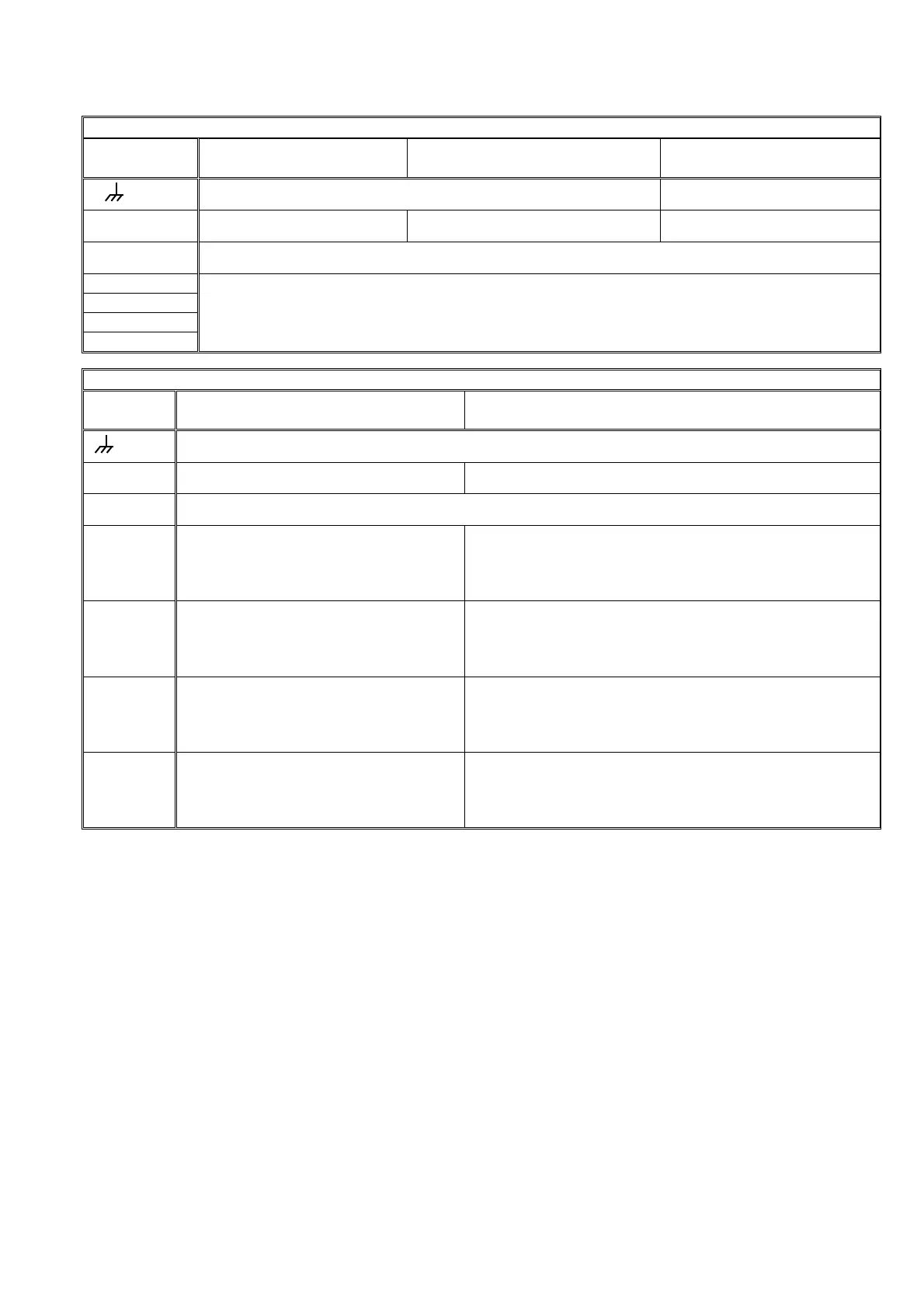
Outlet assignation tables according to unit models.
Model
Outlets Input 230 V or 115 V, Out-
lets 24 V
Input 12 V, Outlets 12 V Input 12 V, Outlets 12 V
Latch Option 3 cables
CP
Box terminal, connected to earth (Built-in model) Stop common
C Outlet common 24 V. Outlet common 12 V. Start common
M Pump/General valve
1-6
1-12
1-18
1-26
Irrigation sectors and general outlets, according to configuration.
Model
Outlets Input 12 V, Outlets 12 V.
Diesel version
Input 12V/230V or 115V, Outlets 12V/24V.
Diesel version with double tension
CP
Box terminal, connected to earth (Built-in model)
C Outlet common 12 V Outlet common 24 V
M Engine starter, position 15/54 of the engine key (12 V)
1-6
6 = Start, 5 = Stop
(Pre-heating / Electro-pump)*
Rest = Sectors and general outlets
6 = Start (12 V), 5 = Stop (12 V)
( Pre-heating** (12V) / Electro-pump (24V) )
Rest = Sectors and general outlets (24 V)
1-12
12 = Start, 11 = Stop
(Pre-heating / Electro-pump)*
Rest = Sectors and general outlets
12 = Start (12 V), 11 = Stop (12 V)
( Pre-heating** (12V) / Electro-pump (24V) )
Rest = Sectors and general outlets (24 V)
1-18
18 = Start, 17 = Stop
(Pre-heating / Electro-pump)*
Rest = Sectors and general outlets
18 = Start (12 V), 17 = Stop (12 V)
( Pre-heating** (12V) / Electro-pump (24V) )
Rest = Sectors and general outlets (24 V)
1-26
26 = Start, 25 = Stop
(Pre-heating / Electro-pump)*
Rest = Sectors and general outlets
26 = Start (12 V), 25 = Stop (12 V)
( Pre-heating** (12V) / Electro-pump (24V) )
Rest = Sectors and general outlets (24 V)
* When any outlet it is used for pre-heating and/or electro-pump, the outlet number occupied will be the afterward
of start and stop outlet of the determined model.
** The pre-heating outlet for equipment with dual voltage option is not standard and must be indicated by
the installer when the equipment is purchased.
4.3. GUIDE TO MALFUNCTIONS
- Valves do not work:
Check the state of the fuses.
Check if any cable is disconnected or cut.
- The equipment does not work properly:
a) There is a black stripe on the screen:
o Disconnect the power supply of the
unit.
o Remove the “J4” bridge (battery bridge)
for one minute.
o Connect the power supply.
o Replace the “J4” bridge.
o Finally assemble the equipment.
b) The screen is completely blank:
Check if the power reaches the equipment.
Check the state of the fuses.
- The unit fuses the general fuse constantly:
The protector of overloads is short-circuited, it is
necessary to replace it. This happens when the
unit is supplied at 380V, for example, or there is
an overload due to a storm and the “general
fuse” is superior to the one indicated in the sec-
tion about technical characteristics.
 Loading...