BATTERY POS. +
AC NEUTRAL IN
(WHITE)
AC GROUND IN
(GREEN)
BATTERY NEG. -
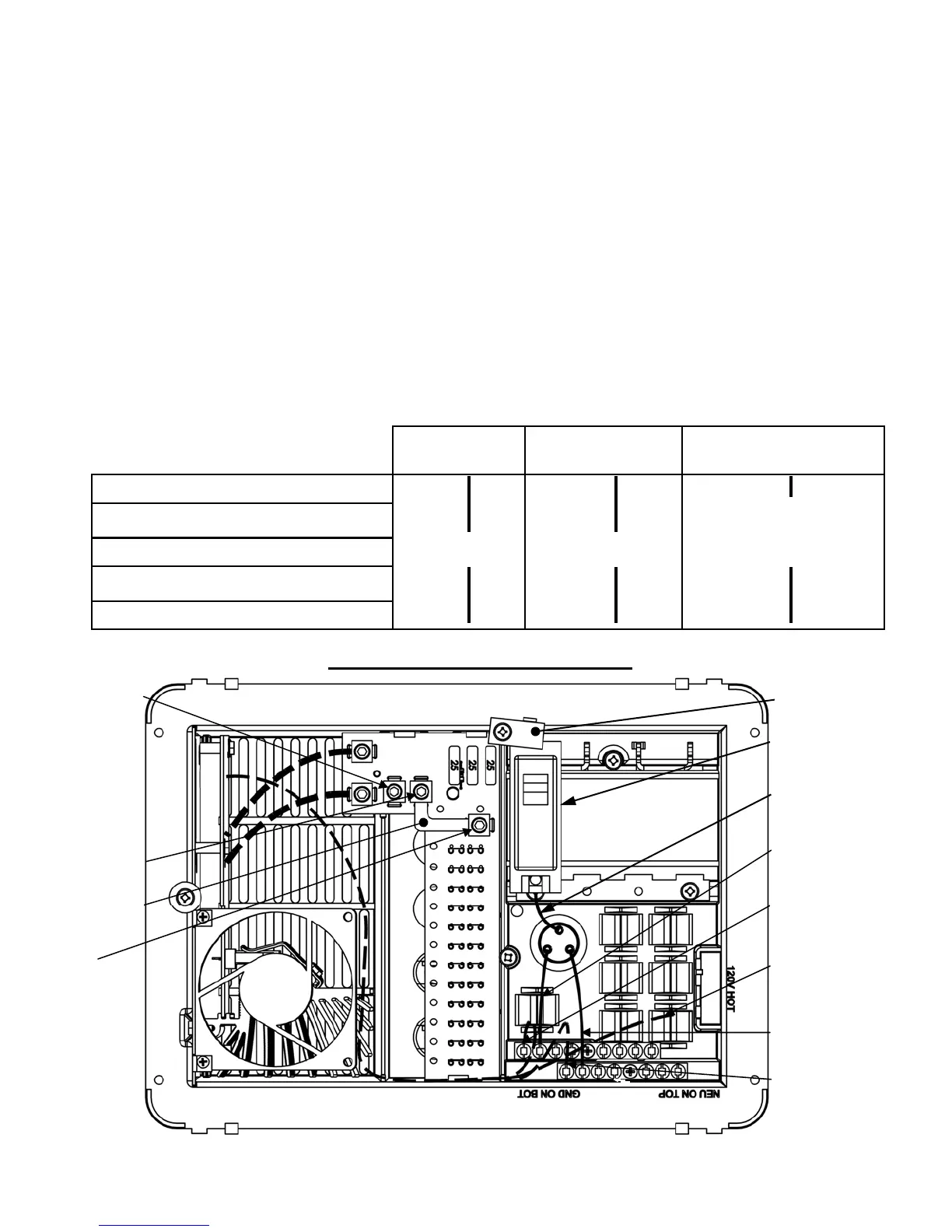
Detailed Wiring Diagram
Note: Above image may vary, depending on model.
AC NEUTRAL
(WHITE)
TO CONVERTER
MAIN BREAKER
HOLD DOWN
AC HOT
(BLACK)
TO CONVERTER
Note: Some factory installed wiring not shown for clarity.
ALTERNATE
BATTERY POS. +
(DC DISCONNECT)
MAIN BREAKER
(NOT SUPPLIED)
AC HOT IN
(BLACK)
AC IN GROUND
(GREEN)
TO CONVERTER
JUMPER
Page 1
Installation Instructions
The following breakers are suitable for
MAIN and BRANCH breakers
MAIN Branch Filler Plate
ITE/Siemens—QP,QT
Thomas & Betts—TB & TBBD Series
ITE/Siemens QF3
Square D—HOM, HOMT
30A 15A GE TQLFPI
Cutler Hammer/Bryant—BR,BRD Series
GE—HACR
Consult a licensed electrician or an RV technician for installation assistance
The PD4000 series POWER CONTROL CENTER should be installed horizontally (converter section to the left).
Unit is NOT ignition protected. Do not mount in the LP gas or the battery compartment.
Cut mounting hole to approximately 10 3/4” wide X 7 1/4” high.
Connect wiring system using proper connections and appropriately sized cable clamp. A closure plug kit for any unused Romex
connectors may be purchased from Progressive Dynamics, Inc. Part Number PD812374.
For installations without an external DC disconnect switch connect battery POS (+) to the BATTERY POS. + lug. The ALTER-
NATE BATTERY POS. + lug is not used. (see wiring diagram for lug locations)
DC DISCONNECT: For installations incorporating an external DC disconnect switch, connect battery POS (+) and the
BATTERY POS. + lug to the same pole on the external disconnect switch. Remove the JUMPER. Connect the ALTERNATE
BATTERY POS. + to other pole on the external disconnect switch. (see wiring diagram for component locations)
The OEM should test the POWER CONTROL CENTER converter under full load conditions in its intended mounting location to
ensure proper ventilation. Failure to provide adequate ventilation will prevent the converter from supplying full output power.
The INTELI-POWER converters are not designed for zero clearance compartments.
The POWER CONTROL CENTER is not designed for wet or damp locations. Install in an interior / dry location.
 Loading...