7
ASSEMBLY INSTRUCTIONS
5
4
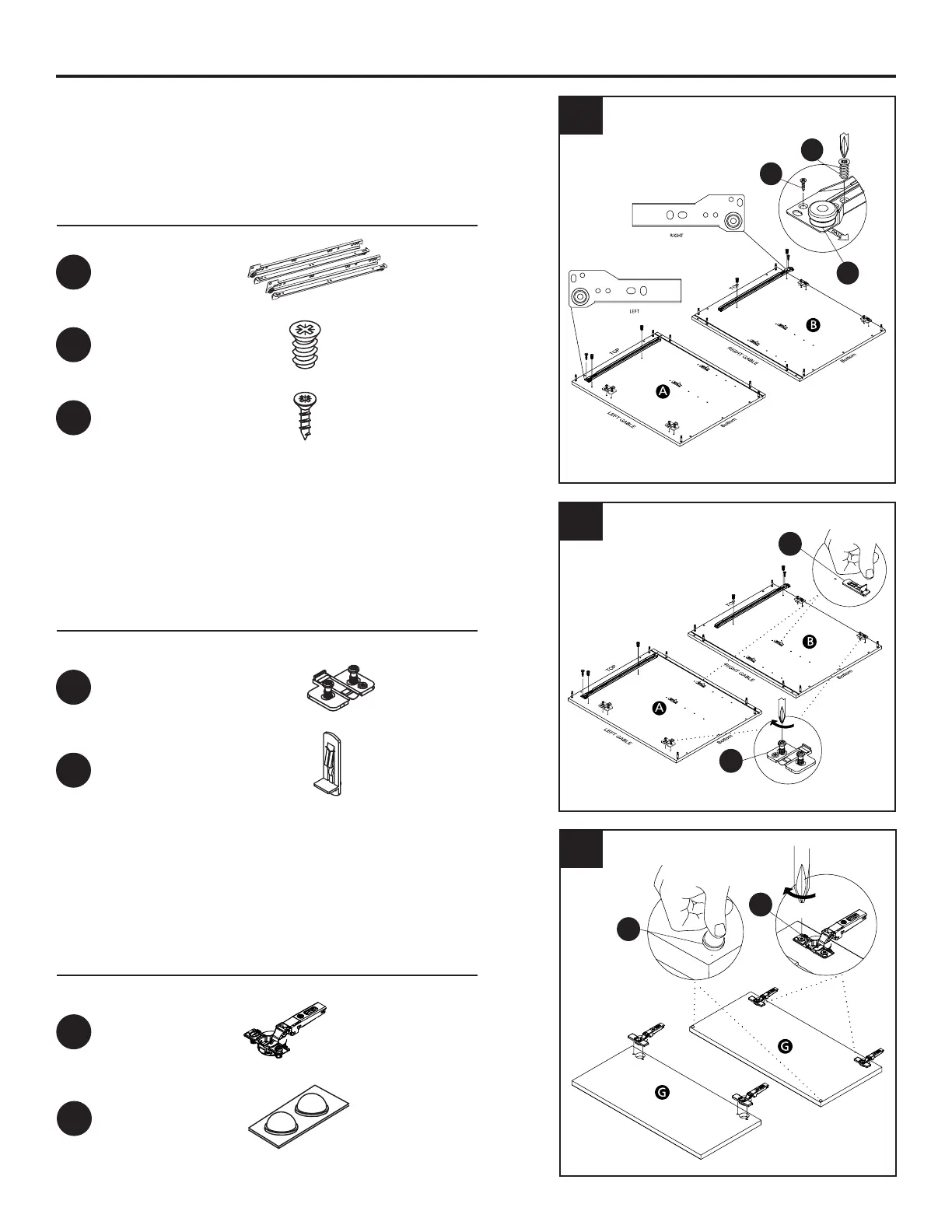
5. Using a phillips head screwdriver, attach the
mounting plate as shown in the illustration.
Insert the shelf support hardware on the
required hole
6
Hardware Used
CSK screw 5/8"
x 2
HH
Euro screw 1/2"
x 4
LL
Hardware Used
Hardware Used
Hinge mounting plate
105
o
Hinge
x 4
x 2
FF
GG
Bumper 2MM
x 4
KK
Epoxy runner
x 1
CC
Shelf support clear
x 4
MM
4. Place the epoxy runner in the correct position as
per the illustration. Use the euro and csk screws
as shown. Ensure the left & right hardware slides
are placed on the correct panels.
6. Insert the hinge in the bore hole. Using a phillips
head screwdriver, turn the pre-installed screws
clockwise to lock into place.
Place the bumper on the door as shown.
HH
LL
CC
FF
MM
KK
GG