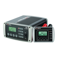
Positively earthed
Connect the BLACK lead (battery clip) from the charger to the Negative (-) battery terminal.
Connect the RED lead (battery clip) from the charger to the vehicle’s chassis away from the
fuel line or moving parts.
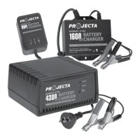
STEP 2C - CONNECTION IN VEHICLE WITH HARNESS (AC150 & AC250B ONLY)
Connect the RED ring terminal of the harness to the Positive (+) battery terminal.
Connect the BLACK ring terminal of the harness to the Negative (-) battery terminal.
Connect the plug on the harness to the charger’s output lead socket.
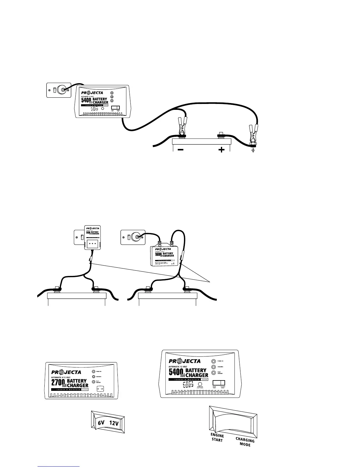
STEP 3 - BATTERY CHARGER SETTINGS (AC400 & AC800 ONLY)
Set the voltage selection switch to either 6V or 12V (AC400)
Set the ‘Charge/Engine Start’ switch to the ‘Charging’ position (AC800).