8
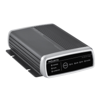
HOW TO READ LED DISPLAY
Input LED (bi-colour)
YELLOW: Input battery is correctly connected.
RED: Input battery is reverse connected (Note: input fuses have blown). Check battery
connections and replace internal input fuses.
Output LED (bi-colour)
YELLOW: Output battery is correctly connected.
RED: Output battery is reverse connected (Note: output fuses have blown). Check battery
connections and replace internal output fuses.
Fault LED
RED: A fault has been detected. Check internal fuses are intact and wiring to the DC20
is correct. If fault LED is still on the unit is damaged. Do not attempt to repair.
Charging LED
YELLOW ON: Charging.
YELLOW ON & GREEN FLASHING: Charger is in ‘absorption’ mode. Charging is almost complete.
Fully Charged LED
GREEN: Battery is fully charged. The charger is in float mode and
can be left connected without risk of overcharging.
Charging & Fully Charged LEDs Flashing
The charger has exceeded the 12 hour (bulk) timeout and has stopped charging.
Reset by disconnecting and reconnecting ignition connection.
HOW TO CHANGE INTERNAL FUSES
1. Determine which fuses need replacing (i.e. input or output fuses).
Refer to previous section “How To Read LED Display”.
2. Disconnect the wires from the DC20 connections and remove the DC20 from its mount.
Take note of input/output wires for easier re-installation.
3. Change fuses. For input fuses go to step (a), for output fuses go to step (b):
a. INPUT FUSE REPLACEMENT
Remove the screws from the back of the DC20. Remove and re-fit 2 x 20A fuses.
Replace back of the DC20.
b. OUTPUT FUSE REPLACEMENT
Remove the screws from the front of the DC20. Remove and re-fit 2 x 15A fuses.
Replace front of the DC20.