Beta Draft Confidential
14 Proliphix Internet Managed Thermostat (IMT) Installation Guide
Part No. 600-03100-000, Rev. 4
Installing and Wiring the Thermostat
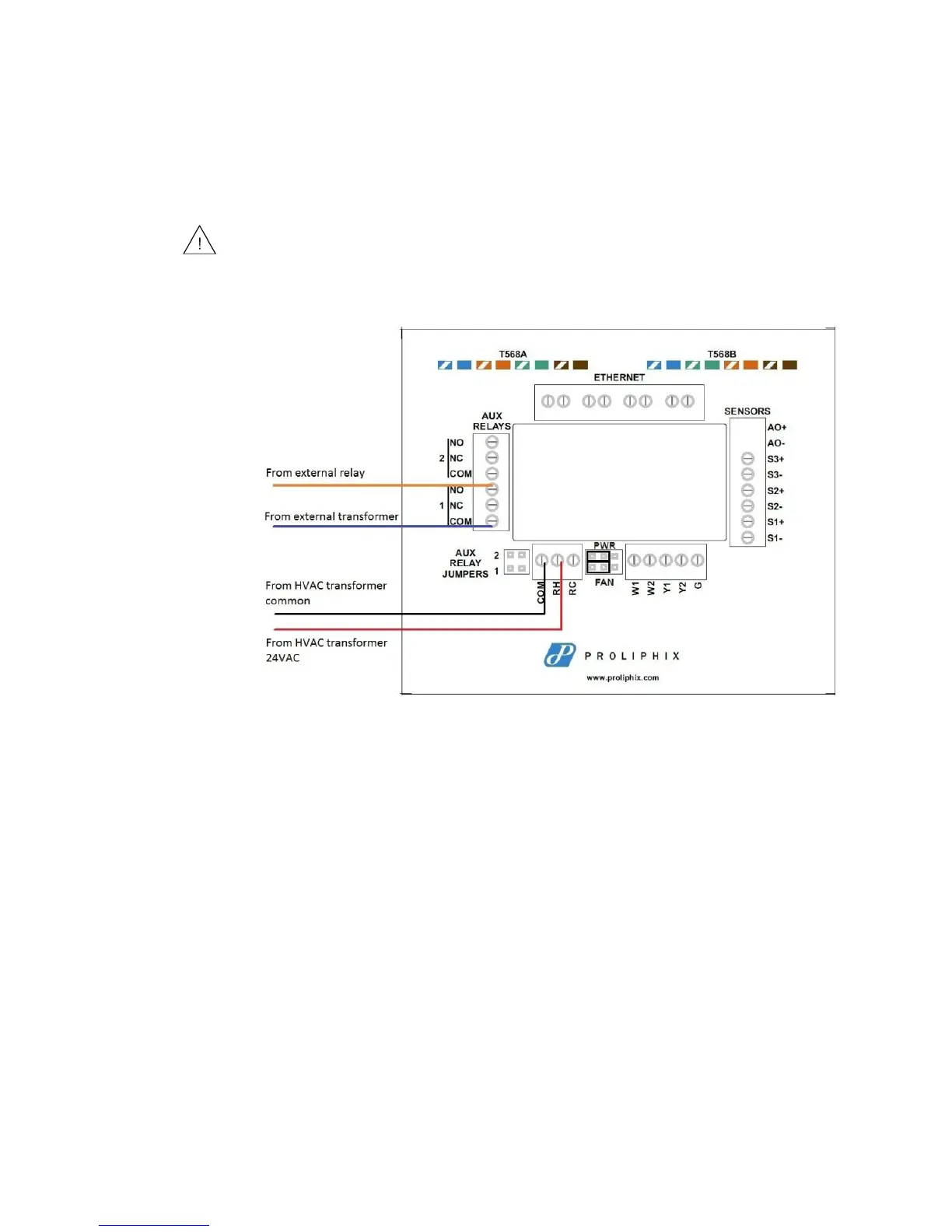
In this type of setup, the installer connects one wire to the Aux Relay COM
connection on the Auxiliary Relay terminal block and the other wire is connected to
either the Normally Open (NO) or Normally Closed (NC) terminal block on the
IMT550 backplate. In most cases, the installer connects to the NO side so when the
relay is not active it stays in an open circuit state. Figure 8 depicts backplate wiring.
Figure 8 Wiring Diagram of Relay Setup Using Additional Transformer
When using an aux relay with an external power source, the jumper (shorting plug)
must be removed to isolate the HVAC power source from this circuit.