Beta Draft Confidential
18 Proliphix Internet Managed Thermostat (IMT) Installation Guide
Part No. 600-03100-000, Rev. 4
Installing and Wiring the Thermostat
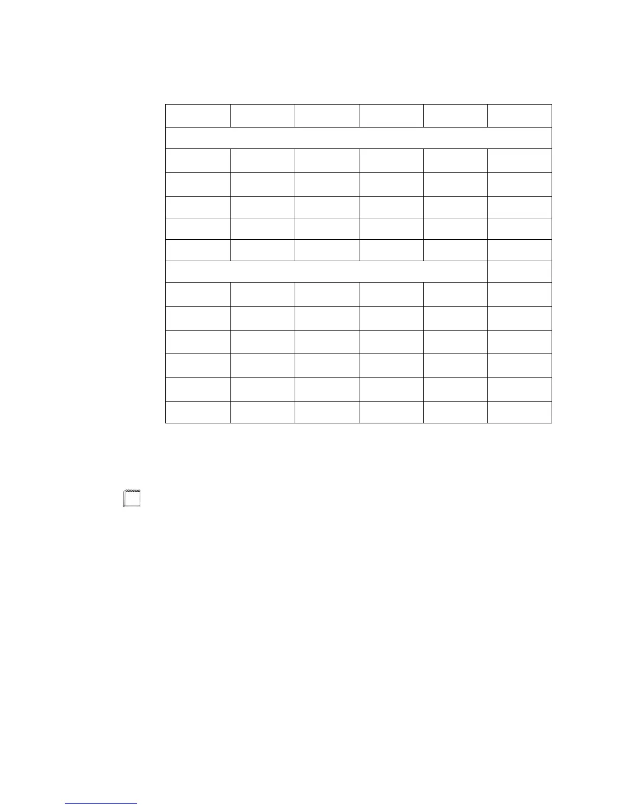
Table 7 describes what relays are active for the HVAC and fan state.
Table 7 Relay Matrix
W1 W2 Y1 Y2 G
Fuel Burner
Heat1 (1h) X
X
a
a
If fan on heat is enabled.
Heat2 (2h) X X
X
a
Cool1 (1c) X X
Cool2 (2c) X X X
Fan X
Heat Pump
Heat1 (1h)
X
b
b
If Heat Pump is a model which activates the reversing valve (B) for heat mode.
XX
Heat2 (2h)
X
b
XXX
Aux Heat (3h) X
X
b
XXX
Cool1 (1c)
X
c
c
If Heat Pump is a model which activates the reversing valve (O) for cool mode.
XX
Cool2 (2c)
X
c
XXX
Fan X
Aux Heat is the last stage whether you have a single or dual stage heat pump.