
M
Melissa HarperAug 13, 2025
What to do if Prology CMD-150 doesn't turn on and car's engine switch is not on?
- BbrittanymarquezAug 13, 2025
Turn your car's key to the ACC or ON position.
What to do if Prology CMD-150 doesn't turn on and car's engine switch is not on?
Turn your car's key to the ACC or ON position.
What to do for a disc mechanism error in Prology CMD-150 Car Stereo System?
First, try pressing the eject button to remove the disc. If the disc cannot be ejected, press the RESET switch and then press the eject button again. If the disc still does not eject, consult your dealer.
Why is there so much noise in Prology CMD-150 broadcasts?
The station may be too far away, or the signals may be too weak. Try selecting other stations with a higher signal level.
What to do if disc sound skips or tone quality is low in Prology CMD-150 Car Stereo System?
The disc may be dirty or damaged. Clean the CD or try another CD.
Why does the sound skip in my Prology CMD-150 due to vibration?
Sound skipping due to vibration can occur if: 1. The mounting angle is over 30 degrees. Adjust the mounting angle to less than 30 degrees. 2. The unit is not securely mounted. Mount the unit securely with the mounting parts.
What to do if my Prology Car Stereo System disc is dirty or damaged?
Clean the disc or try another disc.
What to do if there is no sound when a disc is inside Prology CMD-150?
This could be because the disc is not a CD or does not contain MP3 files, or the disc is upside down. Place the disc in the correct direction with the label side up.
What to do if checking volume or mute on/off doesn't help in Prology Car Stereo System?
If adjusting the volume or mute settings doesn't resolve the issue, press the RESET button.
Details power supply, output, dimensions, and weight specifications.
Covers FM frequency range, usable sensitivity, and audio characteristics.
Specifies frequency response, signal/noise ratio, and distortion for the disc player.
Lists physical components and accessories included with the unit.
Describes the setup for FM tuning measurements using specific equipment.
Details the measurement setup for AM tuning, including Faraday cage use.
Outlines the measurement setup for CD playback functionality.
Basic principles for handling chip components and PCBs.
Step-by-step guide and tools for removing chip components.
Procedures for soldering and attaching components to the PCB.
Safety tips and visual examples for proper chip component handling.
Information on ESD susceptibility and general handling precautions.
Procedures for grounding and maintaining potential equalization.
Warning regarding invisible laser radiation when the unit is open.
Illustrates connection points, connector pinouts, and cable functions.
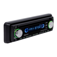
Explains the functions of buttons and controls on the unit's front panel.
Describes the operational functions of the remote control unit.
Instructions for saving and recalling radio station presets automatically.
Procedures for setting the clock and navigating through system menus.
Options for selecting DSP sound effects and radio seek modes.
Details on different volume adjustment modes, including last volume.
Guide on how to search for specific tracks by entering their number.
Instructions for searching and playing files within folders.
Method for finding tracks by searching for characters in their names.
Overview of the remote control's buttons and primary functions.
Step-by-step instructions for replacing the remote control battery.
Safety precautions and warnings related to remote control battery usage.
Procedures for cleaning discs and the disc lens for optimal playback.
Guidance on cleaning tape heads and related parts.
Basic troubleshooting steps for power and sound issues.
Common issues and solutions related to disc playback errors.
Solutions for problems concerning radio reception and noise.
Explanation of various error codes displayed by the unit.
Procedure for removing the main unit's short sheet, covers, front cabinet, and CD loader.
Visual references illustrating specific service states A and C.
Visual references illustrating specific service states B and D.
An overview of the unit's functional blocks and their interconnections.
Details on the wiring and connections for the servo board.
Information regarding the pin connections for the LCD display.
Mapping of pin numbers to specific display segments.
The detailed schematic diagram of the key board components.
Component placement diagram for the top side of the key board PCB.
Component placement diagram for the bottom side of the key board PCB.
A comprehensive list of electrical components used on the key board.
The schematic diagram detailing the servo board circuitry.
List of electrical components specific to the servo board.
Component layout illustration for the top side of the servo board PCB.
Component layout illustration for the bottom side of the servo board PCB.
A comprehensive list of electrical components used on the servo board.
The schematic diagram detailing the main board circuitry.
List of electrical components specific to the main board.
Component layout illustration for the top side of the main board PCB.
Component layout illustration for the bottom side of the main board PCB.
Detailed list of electrical components for the main board (Part 1).
Continuation of the detailed electrical component list for the main board (Part 2).
An exploded view illustrating the breakdown and assembly of the main unit.
A detailed list of all mechanical parts used in the unit assembly.
| Maximum output power | 4 x 50 W |
|---|---|
| Audio formats | MP3, WMA |
| Front panel inputs | USB, AUX |
| Display type | LCD |
| Bluetooth | No |
| Aux Input | Yes |
| Video Playback | No |
| Equalizer | Yes |
| Steering Wheel Control | No |
| Rear View Camera Input | No |
| Supported media | USB |
| Display | Yes |
| USB Port | Yes |