PROLYTE PRODUCTS GROUP © 2001
Prolyte has made every effort to ensure the accuracy of this manual, no liability will be accepted for errors. Prolyte reserves the right to change or alter
their products or manuals without prior notice. No part of this manual may be reproduced in any form or by any means without prior written permission.
PROLYTE PRODUCTS GROUP - phone +31 (0)594 85 15 15 - fax +31 (0)594 85 15 16 - www.prolyte.com
pages 5 of 12
Performance in aluminium
Manual-MPT Tower
Inspect all components before using them on visual wear & tear, deformation, damage or any
other shortcomings. NEVER use parts or component that are not visually correct or you suspect
have been subject to other damage.
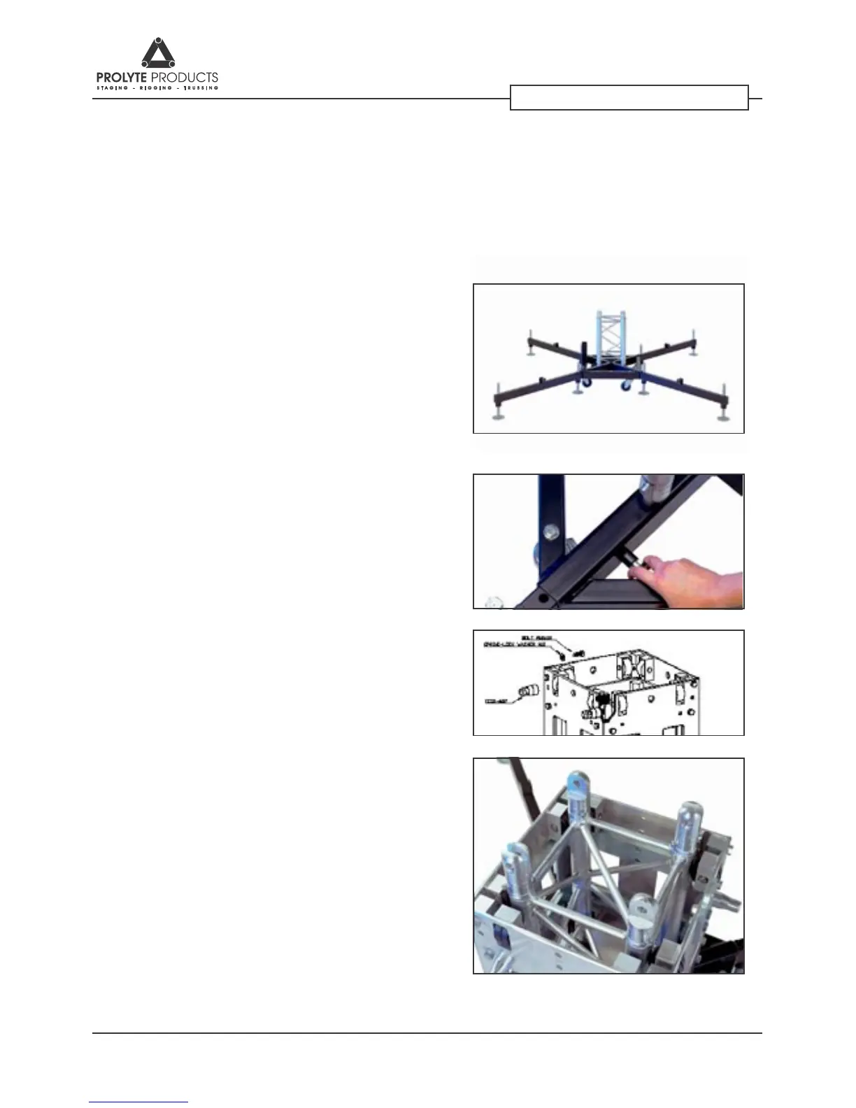
The base section is equipped with 4
castors and 4 half conical couplers (CCS6-
602) for the attachment of the mast
section. The base can be used with either
short or long outriggers. Put the base
sections in the desired positions and place
the rst mast sections on top.
To secure the outriggers within the base,
a trigger pin is placed on the inside of the
base frame. Pull the pin outwards when
mounting the outriggers.
Mount the CCS6-602 male connectors
onto the holes corresponding with the
truss you want to use as span.
Place the sleeve block over this rst mast
section. Disassemble the hinge-set, mount
the half hinges to both the mast sections.
Male and female connections should be
mounted diagonally (see picture), in order
to facilitate the erection of the mast.
1
2
3
4
5