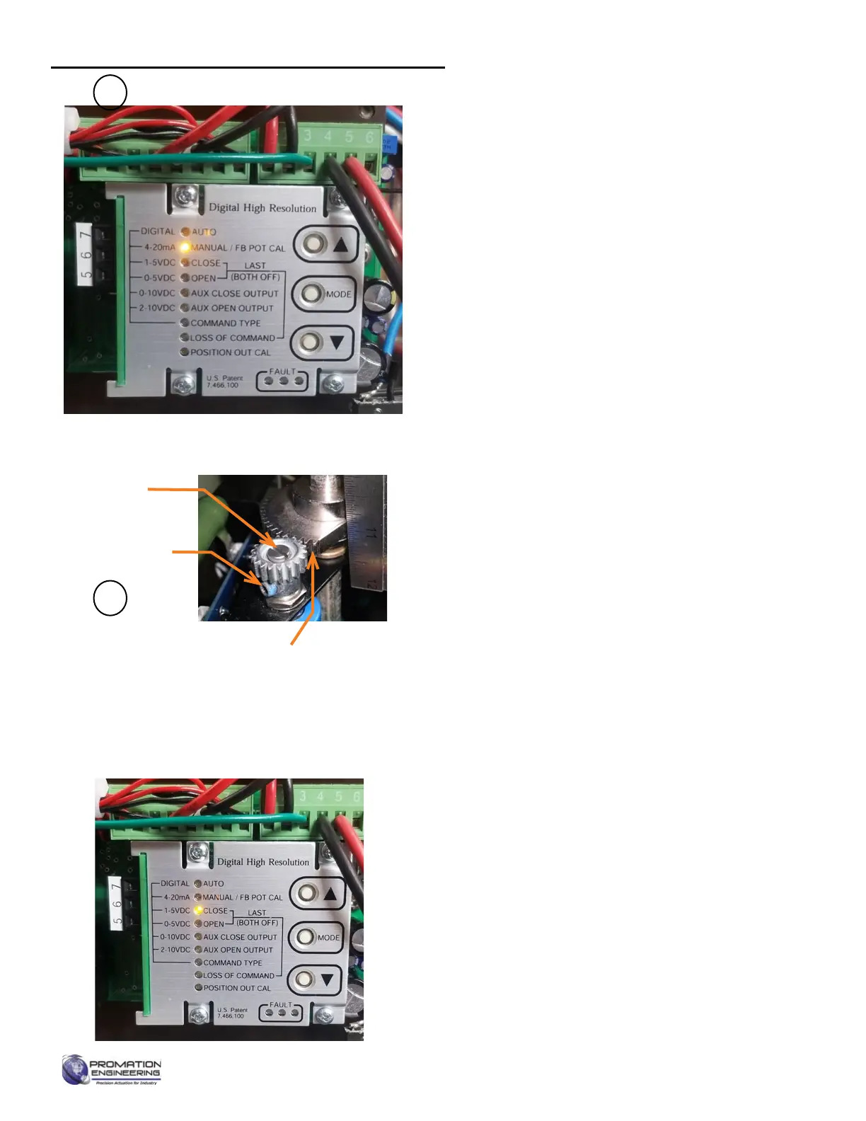
Calibration Interface Notes
The AUTO LED is lit during normal operation. Pressing MODE
will enter the calibration sequence to change operational
parameters. The MODE sequence goes in one direction.
Each time MODE is pressed the current parameter is saved
and the next one is presented. One can cycle through the
operational parameters without changing them by pressing
MODE repeatedly.
Begin Calibration
1. Apply Line Power - The AUTO green LED will light
2. Press MODE until MANUAL/FB POT CAL LED is
lit.
• You may calibrate this as often as needed but it
mayaecttheCWandCCWendpositionsifit
changes.
3. Use▲and▼orhandwheeltopositiontheactuator
to the mid position (i.e. 50% open or 12 mA).
• Blinking amber MANUAL/FB POT CAL light
means you need to adjust the potentiometer
position.
4. Feedback Potentiometer Calibration
(FB POT CAL
LED is blinking).
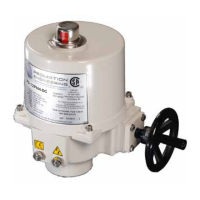
4.A Check Potentiometer Gear Engagement as
shown.
4.B Loosen the potentiometer shaft hex screw. Use
a screwdriver to adjust the potentiometer shaft
until the amber LED is steady.
NOTE: The amber LED blinks more rapidly as you approach
the proper mid position. The farther from that position, the
slower the blinkrate.
5. Set Closed (CW) Position (CLOSE LED is lit)
5.A The motor will drive to approximately the 25%
position.
5.B Use the handwheel or the ▲ and ▼ toposition
the actuator in the desired CLOSE position (i.e.
4mA).(Youmusttoucheither▲or▼beforethe
handwheel responds).
5.C Press MODE to conrm setting. This will also
move you to the next user input setting.
5.D This CLOSE position is now set.
5.E If the AUX CLOSE OUTPUT LED is lit, ignore it
5.F OPEN LED is lit.
Potentiometer Gear Engagement
When the actuator is at CW position, the potentiometer
pinion gear and the camshaft sector gear should
not be past the point of engagement. If the sector
gear should have at least 2 full teeth contacting
the potentiometer pinion gear. If not, contact your
distributor for mechanical recalibration instructions.
Hex Screw
Potentiometer
Shaft
2
4
Calibrating the proportional control board
Page 9 of 17 P2/3 12 24 VDC Proportional Series
FM_P28 24 PN4-DC Ver E 080223