This procedure will assume that the actuator is installed correctly both mechanically and electrically with correct
POWER and SIGNAL, the cams are factory set 1-2° beyond 0° and 90°, and the mechanical stop screws are out.
This proportional control card has been
calibrated and tested at the factory to operate
between 0 degrees and 90 degrees operating
range.
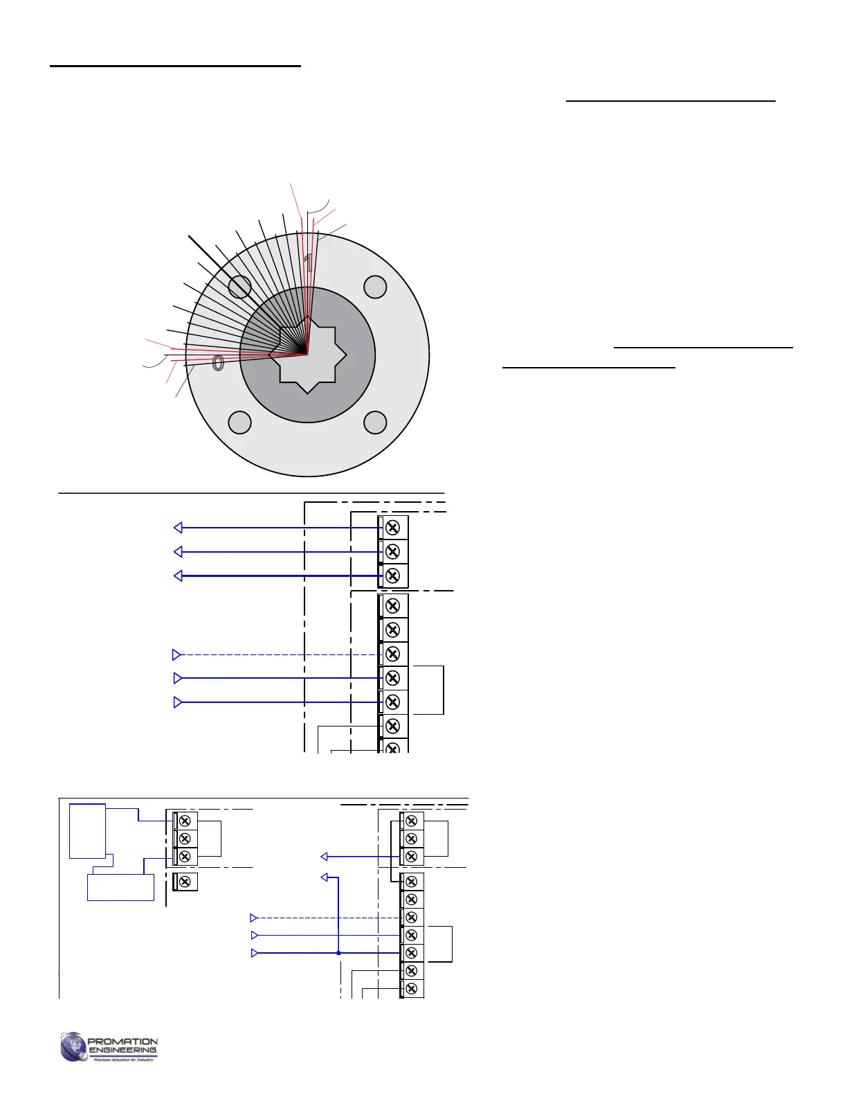
END OF TRAVEL
• Test the travel of the actuator with the handwheel
by rotating from 0° to 90° and listen/feel for the
change of state of the limit switches. If Cams 1
and 2 are outside the desired range of travel,
skip step 2.
• Set cams per the Setting Limit Switches and
Auxiliary Switches (Cams) section:
• Cam 1 for approximately -1°.
• Cam 3 for approximately 3°.
• Cam 2 for approximately 91°.
• Cam 4 cam for approximately 87°.
The open and close end of travel cams (Cam
1 and Cam 2) must be set outside the desired
range of travel of the proportional card. If they
trip, the proportional card stops the motor and
reports a stall condition.
Connect Signal, Feedback and Power per wiring
diagram:
• Signal - (Optional) 4-20mA in uses Terminal 5
(+) and 4 (-) and 0-10V in uses Terminals 7
(+) and 5(-) on J2
• Feedback - The HR feedback option for 24AC,
120AC and 230AC is self powered. 4-20mA
out uses Terminal 6 (+) and 5 (-). 0-10V out
uses Terminals 7 (+0 and 5(-). Use a known
accurate meter to calibrate.
• Feedback - The HR-ISO option and feedback
for all 12 and 24VDC controllers utilizes loop
(external) power. THe power can come from
the board via terminal 8 or from an external
power source.
• Apply line power.
• The AUTO green LED will light.
• The Red AUX POSITION OUT LED will blink
if there is no control signal.
0
SW4 Aux Switch
SW2 CW Limit Switch
CCW Mechanical Stop
Controller CW
End of Travel
Controller CCW End of Travel
SW3 Aux Switch
SW1 CW Limit Switch
CW Mechanical Stop
10
20
30
40
45
50
60
70
80
90
NOT OPEN*
OPEN COM*
OPEN*
NOT CLOSED*
CLOSED COM*
CLOSED*
12
11
10
9
8
7
M
SW3
SW4
THERMAL
SWITCH
AC DRIVE
MOTOR
AUXILIARY
SWITCH
(STANDARD)
AUXILIARY
SWITCH
(STANDARD)
* CONNECTIONS
OPTIONAL
GND Screw
Actuator ships in fully closed position!
Items within dotted line indicates internal components
6
5
4
3
2
1
J1
HEATER
SW1
SW2
J2
E1
E2
J3
1
12 43
430-10100 Switch Card
BLK
RED
WHT
BLK
WHT
Capacitor
ProMation
F
NONE
Use For:
WD-850-P4222 F
5
4
3
2
1
ANALOG
ALL SWITCHES
SHOWN WITH
ACTUATOR IN
FULL OPEN
POSITION
Close
POSITION
FEEDBACK
1K ohm
J4
FACTORY
CONNECTOR
430-10102 Controller
GRY
ORG
BLU
J2
GND
L1 Hot
L2 Neutral
DHC-100
OTX-100
1
2
3
4
5
J1
6
4 3 12
SIGNAL IN
FEEDBACK OUT
(-)
+4-20mA
GND(-)
Amperage Out +4-20mA
WHT
BLK
BLU
RED
8 (+15v OUT)
7
6
GRN
WHT18
(+) 1-5, 0-5, 0-10vdc
ALTERNATE SIGNAL IN
5
7
6
Voltage Out
NOT OPEN*
OPEN COM*
OPEN*
NOT CLOSED*
CLOSED COM*
CLOSED*
12
11
10
9
8
7
M
SW3
SW4
THERMAL
SWITCH
AC DRIVE
MOTOR
AUXILIARY
SWITCH
(STANDARD)
AUXILIARY
SWITCH
(STANDARD)
* CONNECTIONS
OPTIONAL
GND Screw
P(2-8)-120PN4(7)-HR-ISO
Actuator ships in fully closed position!
Items within dotted line indicates internal components
6
5
4
3
2
1
J1
HEATER
SW1
SW2
J2
E1
E2
J3
1
1 2 43
430-10100 Switch Card
BLK
RED
WHT
BLK
WHT
Capacitor
ProMation
F
NONE
Use For:
WD-850-P4221 G
5
4
3
2
ANALOG
ALL SWITCHES
SHOWN WITH
ACTUATOR IN
FULL OPEN
POSITION
Close
POSITION
FEEDBACK
1K ohm
J4
FACTORY
CONNECTOR
430-10102 Controller
GRY
ORG
BLU
J2
GND
L1 Hot
L2 Neutral
DHC-100
+
-
ANALOG
SIGNAL IN
Internal Power
FEEDBACK
(-)
+4-20mA
-
4-20mA
7
6
WHT18
(+) 1-5, 0-5, 0-10vdc
ALTERNATE
SIGNAL IN
+
-
ANALOG
8
4-20mA
MONITOR
DC
Power
Supply
+
-
+
-
Isolated Power
FEEDBACK
4-20mA
+
HR AC- Self Powered
-ISO AC and DC - Loop Powered
Pre Calibration Preparation
Calibration - End of Travel, Feedback
Page 8 of 17 P2/3 12V 24DC Proportional Series
FM_P28 24 PN4-DC Ver E 080223
 Loading...