MI C CHAN NEL 1
LI NE/ CD PH ONO /CD PH ONO /LI NE P HON O/LIN E
MA STER L EVE L
SU RRO UND
MIN MAX
-12 dB
+12 dB
TR IM
HI GH
-12 dB +12 dB
-12 dB +12 dB
MI D
LO W
EQ
MIN MAX
-32 dB +12 dB
TR IM
HI GH
-32 dB +12 dB
-32 dB +12 dB
MI D
LO W
EQ
MIN MAX
-32 dB +12 dB
TR IM
HI GH
-32 dB +12 dB
-32 dB +12 dB
MI D
LO W
EQ
MIN MAX
-32 dB +12 dB
TR IM
HI GH
-32 dB +12 dB
-32 dB +12 dB
MI D
LO W
EQ
MIN MAX
-32 dB +12 dB
TR IM
HI GH
-32 dB +12 dB
-32 dB +12 dB
MI D
LO W
EQ
MIN MAX
ON
+7
+4
+2
0
-2
-4
-7
-10
-20
-30
L R
A
1 2 3 4
SYN C
LO CK
BE AT
AS SIST
B
1 2 3 4
SYN C
LO CK
BE AT
AS SIST
CH -1 CH -2 CH -3 CH- 4 MA STER EF FECT S
10
9
8
7
6
5
4
3
2
1
0
10
9
8
7
6
5
4
3
2
1
0
10
9
8
7
6
5
4
3
2
1
0
10
9
8
7
6
5
4
3
2
1
0
10
9
8
7
6
5
4
3
2
1
0
CF CURVE
1
2
3
4
TE MPO D IF FE REN CE
TI ME OF FSE T
HI
MI D
LO
KI LL A
HI
MI D
LO
KI LL B
1
2
3
MIC
MAS TER
4
SO URCE
MI C ON
OFF MA X
TA L K
CUE MAS TER
MI X
MIN MAX
LE VEL
PH ONE S
MO D E
STE REO SPL IT
PR OGR AM
SC RO LL
PU SH
SE LECT
MIN MAX
LE VEL
LEF T RIG HT
BO O TH LE VEL
MIN MAX
MA STER B A LANCE
EF FECT S ON
AS SIG N A AS SIG N B
1
2
3
4
MO NIT O R
+7
+4
+2
0
-2
-4
-7
-10
-20
-30
+7
+4
+2
0
-2
-4
-7
-10
-20
-30
+7
+4
+2
0
-2
-4
-7
-10
-20
-30
+7
+4
+2
0
-2
-4
-7
-10
-20
-30
A VC A CON TRO L LED C ROS SFADE R B
CH ANN EL 2 CH ANN EL 3 CHA NNE L 4
MON ITO R CUE
(6)
BEAT ASSIST buttons, the difference in tempo from both channels is illustrated in the form of
a ninecharacter message on the TEMPO DIFFERENCE-LED (24). The extent of the difference
in tempo is indicated by a corresponding swing to the right (signal A is slower) or to the Left
(signal B is slower). When the middle LED lights up, the tempi are the same. The TIME OFF-
SET LED (23) below that displays the signal A and B synchronisation. Should the middle LED
light up, the tracks are synchronised. Should the display move to the left or right, the channels
are not synchronised. The TEMPO DIFFERENCE and TIME OFFSET displays are only active
if the tempi of both channels have been fixed in one of the ways described.
When no signal is present (or when the signal level is too low), the BPM display shows
only dashes. When the signal is present but can not be identified, the display shows 160
BPM and the shows the said dashes. The beat counter then attempts to get another re-
adout. Therefore, 160 BPM is no usable value; rather, it is simply an error message whten
the signal can not be analyzed.
To exit the SYNC LOCK or BEAT ASSIST modes, simply push the SYNC LOCK button once
more on both channels.
1.8 Internal effects processor
EFF
10
11
12
13
14
15
20
21
22
23
24
25
26
27
28
29
A
B
30
31
32
33
34
Reverb
Big Plate
Reverb
Small Chamber
Reverb
Bright Room
Reverb
Voice Widener
Reverb
Phil s Drums
Reverb
Short Delay
Delay
1/2 95 BPM
Delay
3/4 95 BPM
Delay
1/1 95 BPM
Delay
1/2 110 BPM
Delay
3/4 110 BPM
Delay
1/1 110 BPM
Delay
1/2 124 BPM
Delay
3/4 124 BPM
Delay
1/1 124 BPM
Delay
1/2 131 BPM
Delay
3/4 131 BPM
Delay
1/1 131 BPM
Echo
1/2 95 BPM
Echo
3/4 95 BPM
Echo
1/1 95 BPM
Echo
1/2 110 BPM
Echo
3/4 110 BPM
EFF
35
36
37
38
39
A
B
40
41
42
43
44
50
51
60
61
62
70
71
72
73
74
75
Echo
1/1 110 BPM
Echo
1/2 124 BPM
Echo
3/4 124 BPM
Echo
1/1 124 BPM
Echo
1/2 131 BPM
Echo
3/4 131 BPM
Echo
1/1 131 BPM
Flanger
Stereo Flanger
Flanger
Vintage Flanger
Flanger
Dual Phaser
Flanger
Rotary Speaker
Flanger
Stereo Chorus
Panning
Panning
Panning
Tremolo
Filter
Auto Filter
Filter
LFO Filter
Filter
Vinylizer
Sim/Dyn
Ultrabass
Sim/Dyn
Ultrafex
Sim/Dyn
Voice Changer
Sim/Dyn
Tube Amp
Sim/Dyn
Blues
Sim/Dyn
Radio Speaker
(3)
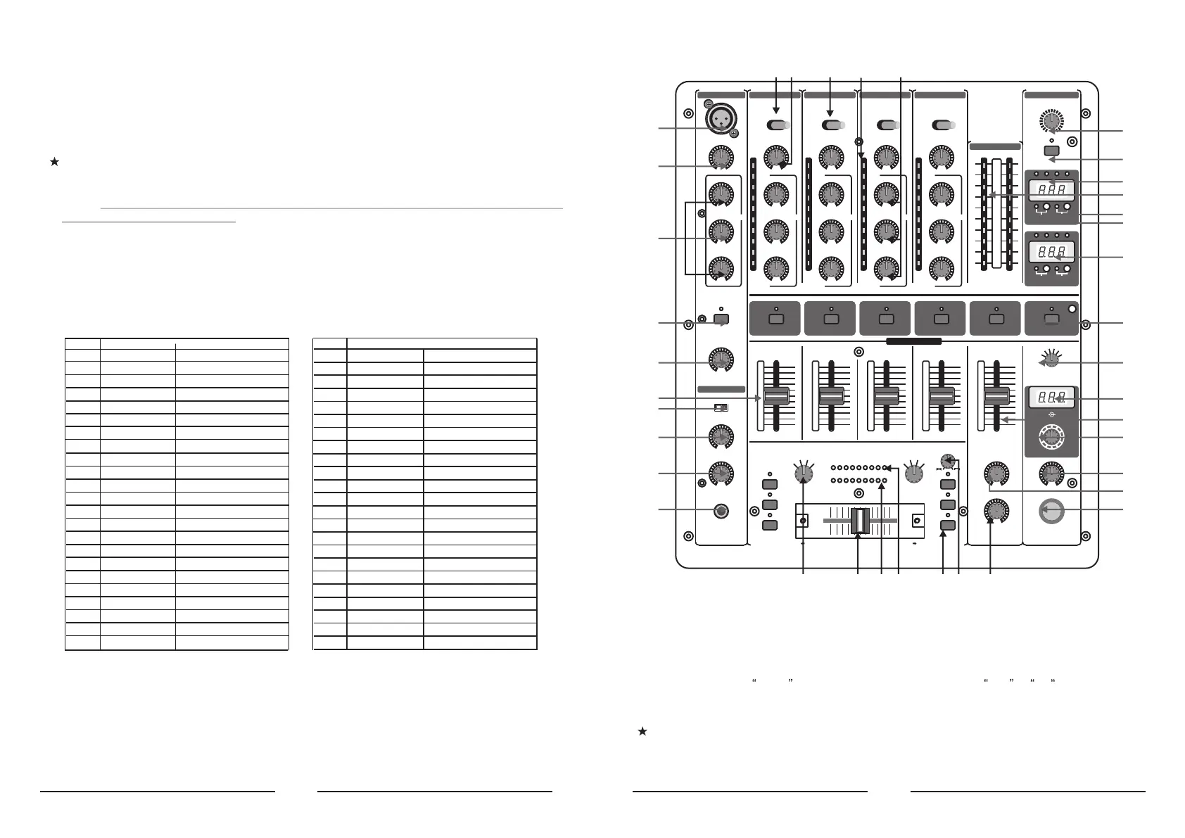
1. CONTROL ELEMENTS
(1) (3) (2) (5) (4)
(6)
(7)(7)
(8)
(9)
(10)
(11)
(16)
(17)
(18)
(37)
(36)
(35)
(33)
(30)
(34)
(32)
(27)
(28)
(29)
(31)
(19)
(12)
(13)
(14)
(15)
(20)(21) (22) (23)(24) (26)(25)
1.1 Stereo channels 1 to 4
(1) Use the LINE/CD switch to select the input signal for channel 1. Unlike other channels, channel 1
features two line inputs.
(2) You determine the input signals for the channels 2 to 4 with the PHONO/CD i.e. PHONO/LINE switch
(channels 3 and 4). Phono is intended for connecting a turntable. Line i.e CD must be selected
for all other signal sources (e.g. CD or MD players). The input sensitivity of the phono input can be
switched to line level, allowing utmost flexibility (see(41)).
Never connect devices with line level to the highly sensitive phono inputs! The output
level of phono pick-up systems is measured in millivolts, whereas CD players and tape
decks have levels measured in volts, i.e.the level from line signals is up to 100 times
higher than that of the phono inputs.
 Loading...