EasyManua.ls Logo

Propex HS2000 - User Manual

Propex HS2000
4 pages
Print Icon
To Next Page IconTo Next Page
Loading...
Page
7
Fault Finding Table for Heaters post 2016
Number
of Flashes
Fault Remedy
1 Flame failure
Check gas
supply making sure there is gas in the bottle
and no blockage in the gas line. Ensure propane is used
at temperatures below +5°C. Clear lockout as
described.
2
Overheat
fault
Hot air temperature is too high. Check the air ducts and
vents are not blocked or restricted. We recommend
you wait at least 5 to 10 minutes to allow the heater to
cool before clearing lockout as described. Check
ducting for blockages.
3
Low/high
voltage
Minimum operating voltage is 10v and max operating
voltage is 15v (for 12v heaters) when measured at the
heater. Check battery voltage. If above 10v, check
connections between heater and battery. Check
alternator or external battery charging. Clear lockout as
described.
4
Combustion
air fault
Check combustion air
flue and exhaust flue for
blockages. Possible blockage in combustion air
inlet/outlet duct. Inspect duct for blockage/damage.
Inspect inlet pipe on the heater (closest to the back) for
signs of damage.
5, 10
Other /
internal fault
lockout
as described
. If this fails,
contact Propex.
Solid General
Two faults have occurred at the same time OR at least
five or more lockout clearing attempts have been
unsuccessful. Clear lockout as described.
No
flashing
PCB not
powered up
Check
the supply to the heater as above. Check fuse
(F1) on main PCB. Otherwise contact Propex
H or C
Too Hot
/
Too cold
Temperature inside the
vehicle is either above 30
°
C
or
below -21°C.
Propex Heating and Leisure Ltd. Unit 10 Carvers Trading Estate, Ringwood, Hants. BH24 1JS
Tel 01425 486950 www.propexheatsource.co.uk sales@propexheatsource.co.uk
Installation and
operating
Instructions
Digital Thermostat
Question and Answer IconNeed help?

Do you have a question about the Propex HS2000 and is the answer not in the manual?

Summary

Fault Finding Table for Heaters

Overview of Digital Thermostat

Heater Compatibility

Package Contents

Thermostat Fault Finding

No Thermostat Response

Heater is not powered up. Check heater power supply for thermostat operation.

Unresponsive Keypad

Keys are being pressed too quickly. Use a more positive key action.

Delayed Green LED Indicator

Built-in delay. Wait 2 seconds after desired temperature position is reached.

Heater Fault Reset Issues

Incorrect reset sequence for heater being used or carried out too fast. Check manual.

Installation Guide

Heater Fault Reset Procedure

Operation: Gas Only Heater

Countdown Timer Function

Set countdown timer for heater operation from 1 to 16 hours.

Operation: Gas and Electric Heaters

Overview

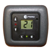
The Propex Digital Thermostat is a sophisticated control unit designed to enhance the operation of Propex or Whale space heaters, providing precise temperature management for recreational vehicles and other enclosed spaces. It functions by measuring the ambient air temperature and activating or deactivating the heater to maintain a desired set temperature.

Function Description:

The primary function of the Digital Thermostat is to regulate the cabin temperature. When the ambient temperature, as measured by the thermostat, falls approximately 2 degrees below the set temperature, the heating function is activated. Conversely, when the ambient temperature reaches the set temperature, the heating function is switched off. This cycle continues until the thermostat is manually turned off.

For gas-only heaters, the thermostat includes a countdown timer function, allowing users to schedule heater operation after a specified delay. For gas and electric heaters, the thermostat offers both gas and electric heating modes, with adjustable power settings for electric operation.

The thermostat features a clear digital display that shows the current ambient temperature, the set temperature, and, in timer mode, the remaining countdown time. LEDs provide visual feedback on the heater's status: a green LED indicates that the thermostat is calling for heat, and a red LED illuminates when a flame is successfully established (for gas heaters) or when a fault occurs.

Important Technical Specifications:

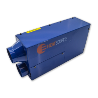
While specific technical specifications like voltage and current ratings are not explicitly detailed in the provided manual, the thermostat is designed for integration with Propex and Whale space heaters. The manual mentions compatibility with various heater models, including:

  • Program 1 (Gas only Heaters): HS2000, HS2800, HS2211
  • Program 2 (Gas or Electric Heaters): HS2000e, HS2202, HS2212

The thermostat is designed to accept the decorative bezel manufactured by CBE in Italy, indicating a standard mounting size and aesthetic compatibility. The installation guide specifies a mounting hole diameter of 22mm for the harness and screw positions for securing the unit. The overall dimensions for mounting are approximately 73mm in width and 18mm in height for the visible part, with a depth of 20mm for the internal components.

The device operates within a temperature range, with fault conditions triggered if the internal vehicle temperature is above 30°C or below -21°C. For 12V heaters, the minimum operating voltage is 10V and the maximum is 15V.

Usage Features:

The Digital Thermostat offers intuitive controls for ease of use:

  • Gas Control On/Off Button: This button powers on the thermostat, illuminates the screen, and displays the current ambient temperature. Pressing it again turns off the heater.
  • Increase/Decrease Temperature Arrows: Located on the left-hand side, these arrows allow users to set the desired room temperature. When an arrow is pressed, the current 'set' temperature is displayed.
  • Timer Select Button (Gas Only Heaters): Pressing this button displays the number of hours for the countdown timer. Repeated presses cycle through 1 to 16 hours. After 5 seconds of inactivity, the timer starts counting down, and the display alternates between hours and minutes remaining. The heater will start automatically once the timer reaches zero. To cancel the timer, press the button again after the countdown has started.
  • Power Level Button (Electric Heaters): For electric operation, pressing and holding this button illuminates the screen and displays the last set power level. Continued holding cycles through available power settings: E1 = 500W, E2 = 1kW, E3 = 2kW. Releasing the button at the desired level sets the heater to operate at that power.
  • Reset Button: Used for clearing fault codes.

Heater Fault Reset:

The thermostat provides visual indication of heater faults via a red flashing LED. To reset a fault, users must first identify the cause by consulting the heater's instruction manual. Once the fault is addressed, the reset procedure varies depending on the heater's manufacturing date:

  • For heaters manufactured from 2016 and prior to April 2018: Ensure the set temperature is above ambient. Press the gas control button ON, then switch it OFF, then switch back ON within 2.5 seconds.
  • For heaters manufactured from April 2018 onwards: Switch the unit off. Locate a small concealed button in the bottom right-hand corner near the display. Using a paper clip, gently press this button twice, leaving 1 second between presses. A QR code is provided in the manual for a YouTube video demonstrating this reset procedure.

Maintenance Features:

The manual primarily focuses on installation and operational aspects, with limited explicit details on routine maintenance. However, the fault-finding table serves as a crucial maintenance aid, guiding users through troubleshooting common issues:

  • No response from thermostat: Check if the heater has power.
  • Not responding to key presses: Use a more positive key action.
  • Thermostat does not immediately bring on green LED: This is due to a built-in delay; wait 2 seconds after the desired temperature is set.
  • Cannot reset fault on heater: This indicates either a wrong reset sequence for the heater or the sequence being carried out too fast. Users should check the heater manual for the correct sequence and ensure a 1-second interval between ON activations.

The fault-finding table for heaters (separate from the thermostat's fault finding) provides detailed remedies for various heater faults indicated by the number of flashes on the thermostat's red LED:

  • 1 Flash (Flame failure): Check gas supply, ensure propane is used below +5°C, and clear lockout.
  • 2 Flashes (Overheat fault): Check air ducts/vents for blockages, wait 5-10 minutes for cooling, and clear lockout.
  • 3 Flashes (Low/high voltage): Check battery voltage (10-15V for 12V heaters), connections, and charging system. Clear lockout.
  • 4 Flashes (Combustion air fault): Inspect combustion air and exhaust flues, ducts, and inlet pipe for blockages or damage.
  • 5, 10 Flashes (Other/internal fault): Attempt to clear lockout; if unsuccessful, contact Propex.
  • Solid Red LED (General fault): Indicates two simultaneous faults or five or more unsuccessful lockout clearing attempts. Clear lockout.
  • No Flashing (PCB not powered up): Check heater supply and fuse (F1) on the main PCB; otherwise, contact Propex.
  • H or C (Too Hot/Too cold): Indicates vehicle temperature is above 30°C or below -21°C.

The design of the thermostat with a removable bezel suggests that it can be easily integrated into various interior designs and potentially replaced or serviced without extensive panel work. The emphasis on referring to the heater's instruction manual for fault identification highlights the integrated nature of the system and the importance of comprehensive documentation for troubleshooting.

Propex HS2000 Specifications

General IconGeneral
BrandPropex
ModelHS2000
CategoryThermostat
LanguageEnglish

Related product manuals