Installation Instructions
1. Install an Inlet Shut Off Valve (Not Supplied)
• Turn off the cold water supply and open the cold water faucet to
relieve any line pressure (see figure 1).
• Install an inlet shut off valve (not supplied) between the existing
cold water supply shut off valve and the kitchen faucet, in a way
that conforms to state and local plumbing codes (see figure 1).
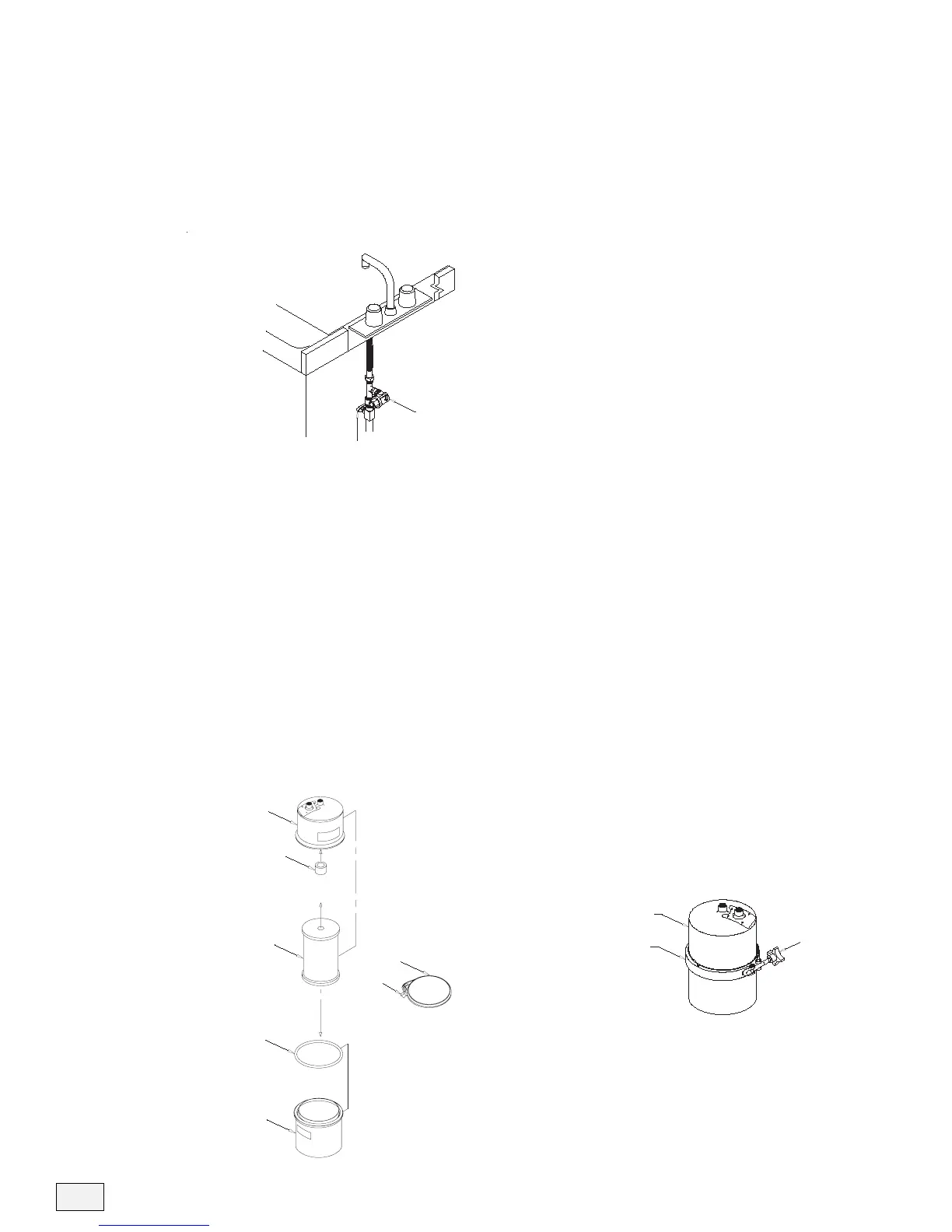
2. Assemble the System
• Remove the filter housing from the packaging.
• Add 1 tablespoon of 5.25% household bleach (unscented) to a
bucket of water. Soak the filter housing, rubber spacer, and o-ring
in the bleach water for 5 minutes.
• Push the rubber spacer onto the threaded stud located inside the
top half of the filter housing (see figure 2).
• Wearing sterile gloves, remove the filter cartridge from the sterile
packaging and screw it onto the threaded stud (see figure 2). DO
NOT OVER-TIGHTEN!
• Lubricate the o-ring with a non-petroleum lubricant and place it on
the bottom filter housing flange (see figure 2).
• Put the top and bottom filter housings together and place the
retainer band on the flanges. Tighten the hand knob until it feels
tight (see figure 3).
4
Important Note: Be careful not to
contaminate the filter cartridge by
touching non-sterile objects.