5.0 3500 Indications and Controls
The 3500 has a comprehensive front panel display enabling the current state of the 3500 to be rapidly
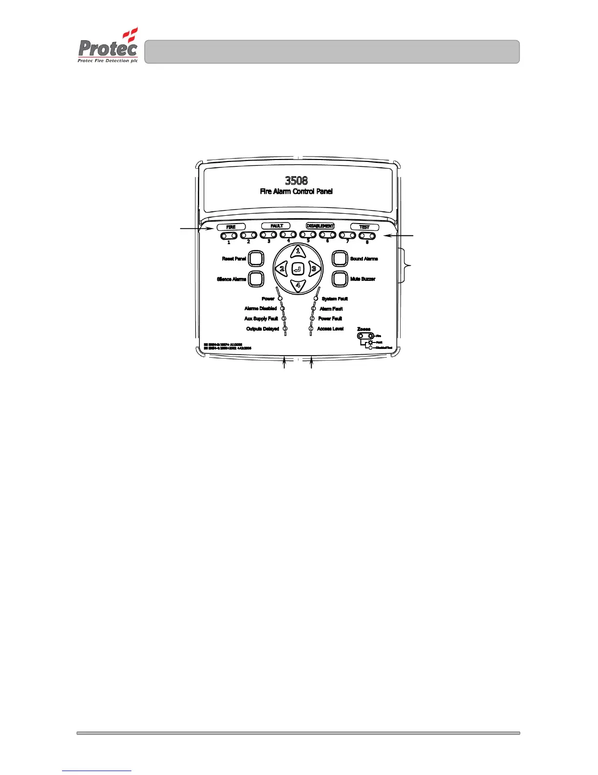
determined. Figure 5.0 shows the indications and controls.
Figure 5.0 3500 front panel indications and controls.
5.1 General Indications
Row 1 comprises the General Fire, Fault, Disablement and Test indicators. These indications give clear
indication that the 3500 has at least one Fire, Fault, Disablement or Test condition.
5.2 Multifunction Zone Status Indications
Zone status indicators are located in row 2 and contain zone pairs, one indicator for fault, disablement, test
and the other indicator for fire.
Zone fires are indicated when the zone indicator flashes red, and are always accompanied by the General
Fire indicator.
Zone faults are indicated when the zone indicator flashes yellow and are always accompanied by the
General Fault indicator.
Zone disablements are indicated when the zone indicator lights steady yellow and are always accompanied
by the General Disablement indicator.
Zones in test mode are indicated when the zone indicator lights steady yellow and are always accompanied
by the General Test indicator.
5.3 Code Entry and Menu Keys
The keys in the centre of the 3500 are used to enter the user code (using keys 1, 2, 3 and 4) and are also
used to navigate the menu system.
5.4 Sound Alarms, Silence Alarms, Reset Panel and Mute Buzzer keys
These keys are used to control panel functions. The user code must be entered before the keys become
operational.